Why Wiring Design Comes Before Cable Selection
A heat trace circuit rarely fails because the cable was wrong. It fails because the wiring plan behind it — circuit length, breaker sizing, voltage drop over the run — wasn't worked out before the cable went on the pipe. By the time a technician is standing at the panel with a multimeter, the mistake is already baked into the layout.
Cable type and wattage get most of the attention in planning discussions, and for good reason — our broader guide to heat tracing system components and selection covers that ground. This piece stays narrower: the wiring itself — how circuits get laid out, how power gets connected, and what code requires before anyone flips the breaker.
Planning Circuit Layout and Power Connections
Heat trace circuits typically run on 120V, 208V, 240V, or 277V single-phase power, though larger industrial loads often move to three-phase to keep circuit lengths manageable and current draw within reason. A constant-wattage three-phase trace heater is the usual choice when a single-phase circuit would need to run too long or draw too much current on one breaker.
Every circuit has a maximum length set by the cable's resistance and the breaker's trip rating — exceed it and the circuit either won't reach full temperature at the far end or will trip nuisance faults under cold-start conditions, when the cable draws its highest inrush current. Before laying any cable, walk the actual route: count elbows, valves, and supports, and add circuit breaks wherever the run would otherwise exceed the manufacturer's maximum length for that voltage and wattage.
Plan power connection points at accessible locations, not buried under insulation or behind permanent structures. A junction box that needs a wrench and a ladder to reach during a cold-weather fault is a box nobody checks until the line has already frozen.
Making the Power Connection
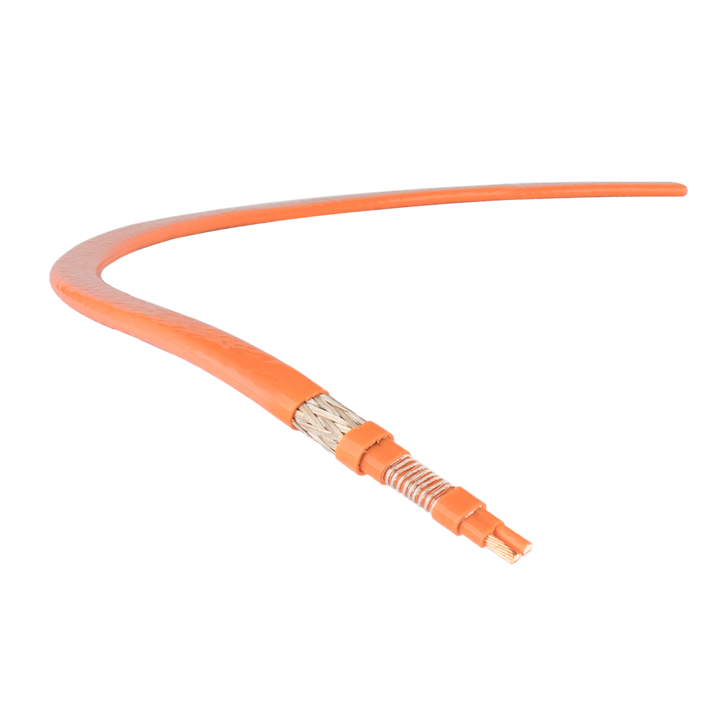
Power connections rely on manufacturer-supplied termination kits rather than field-improvised splices, and for good reason — a heat trace cable's two bus wires and braided overshield each need to land on a specific termination point, and getting that wrong compromises both the heat output and the ground path. Kits rated for water-resistant entry, typically to a NEMA 4X standard, keep moisture out of the junction box where most long-term failures start.
Inside the box, the tinned copper overbraid has to be fully separated from the two internal busbars before termination — a shortcut here is one of the more common causes of nuisance ground-fault trips months after commissioning. Using trace heater installation kits and accessories matched to the specific cable type avoids the mismatched connector problem that shows up disproportionately often in post-installation service calls.
Leave 12 to 18 inches of extra cable at each termination point. Circuits get re-terminated during maintenance more often than most installers expect, and cutting a run too tight the first time turns a five-minute repair into a full cable replacement.
Ground-Fault Equipment Protection Requirements
NEC Article 427.22 requires ground-fault equipment protection (GFEP) on branch circuits feeding electric heat tracing. GFEP trips at a much higher current threshold than a standard GFCI — around 30 mA versus 5 mA — because heat trace cables have some inherent leakage current by design, and a GFCI-level trip setting would cause constant nuisance shutdowns.
Industrial facilities get a narrow exception. If the installation includes an alarm that indicates a ground fault rather than tripping the circuit, and if two conditions hold — qualified personnel maintain the system, and continued circuit operation is necessary for safe process operation — GFEP can be configured to alarm instead of trip. Getting this wrong isn't just a compliance issue; it's the difference between a controlled shutdown and an unplanned one on a critical process line, a distinction covered in more depth by IAEI's technical review of ground-fault monitoring for heat trace systems.
Testing the Circuit Before Energizing
Every heat trace circuit should pass a dielectric insulation resistance test before it ever sees line power. A megohmmeter — rated for a minimum test voltage of 500 Vdc, and commonly run up to 2500 Vdc for polymer-insulated cable — checks the resistance between the cable's conductive core and its outer braid or the metal pipe it's mounted on.
Testing procedures and acceptance thresholds for this step, along with the splice spacing and termination sequencing that precede it, are laid out in detail in our breakdown of construction techniques and inspection standards for electric heat tracing. The same testing sequence and general design practice for resistance-type trace heating installations is codified in IEEE 515, the standard most industrial specifications reference for this work.
A cable that fails this test almost never shows visible damage. The nick in the jacket that let moisture in during installation won't announce itself until the circuit is buried under insulation and already energized — which is exactly why the test happens before, not after, that insulation goes on.
Common Wiring Mistakes That Cause Field Failures
Most heat trace wiring failures trace back to a short list of repeatable mistakes rather than exotic causes:
- Running a circuit past its rated maximum length, which starves the far end of heat and stresses the breaker at cold start
- Terminating in a junction box that isn't rated for the cable's entry type, leaving a path for moisture
- Failing to separate the overbraid fully from the busbars during termination, a frequent source of nuisance ground-fault trips
- Bending cable tighter than its minimum bend radius near fittings, which cracks the insulation without any visible sign at the time
- Skipping the pre-energization megohmmeter test and finding out about a damaged cable only after insulation is installed
Circuits that trip repeatedly on ground-fault protection almost always point back to one of these wiring issues rather than a faulty breaker. Our self-regulating heat trace troubleshooting and maintenance guide walks through how to isolate which of these is actually at fault before pulling the whole circuit apart.
Wiring for Hazardous Area Installations
Wiring rules tighten considerably once heat trace runs into a classified hazardous area — refineries, chemical plants, and offshore platforms being the most common settings. Standard junction boxes and control panels aren't an option here; cable entries, splice kits, and enclosures all need ATEX or IECEx certification appropriate to the zone.
Control wiring is where this shows up most visibly. A control cabinet built for hazardous location heat trace circuits uses sealed entries and certified internal components rather than a general-purpose enclosure retrofitted with better gaskets. Field modifications to a standard panel — drilling new cable entries, swapping glands after the fact — void the certification and turn a compliant installation into a liability, even if the wiring itself looks identical to a properly certified one.

 English
 русский
 Français
 Español
 عربى
عربى
