An electrical heat tracing system works by running a current through resistive or self-regulating cable attached to a pipe, tank, or vessel, generating just enough heat to offset losses to the surrounding air. Get the cable type, control strategy, and insulation right, and the system will hold a target temperature for 10 to 25 years with minimal intervention. Get any one of them wrong, and you end up with frozen lines, nuisance trips, or a control panel nobody trusts.
Core Components That Make Up an Effective System
Every functioning system relies on four parts working together: the heating cable itself, thermal insulation, a protective jacket, and a control or monitoring circuit. The cable is fixed directly to the pipe surface, usually with aluminum tape at set intervals, then covered with insulation and a weatherproof outer layer that keeps moisture and mechanical damage away from the electrical components.
Cable selection sits at the center of this list, since it determines both the heat output and the failure modes you'll deal with later. Options range from self-regulating and constant-wattage heating cables to mineral-insulated cable for higher-temperature process lines. Each type behaves differently under varying pipe lengths, ambient swings, and voltage conditions, which is why cable choice should follow a heat-loss calculation rather than a catalog guess.
Termination kits, splice connectors, and end seals round out the physical build. These small components cause a disproportionate share of field failures — a loose splice or a compromised end seal lets moisture into the circuit, and that's often the first thing a megohmmeter test will flag during commissioning.
How the System Maintains Target Temperature
The underlying principle is straightforward: the cable's heat output has to match or slightly exceed the pipe's heat loss to the environment. Heat loss depends on pipe diameter, insulation thickness, ambient temperature, and wind exposure for outdoor runs. Engineers calculate this in watts per linear foot, then select a cable rated to deliver that output across the coldest expected conditions.
Self-regulating cables adjust their output automatically as the surrounding temperature changes, drawing more current in cold spots and less where the pipe is already warm. Constant-wattage cables don't self-adjust, so they depend entirely on a thermostat or control system to cycle power on and off. This distinction matters more than most buyers realize — a self-regulating cable on a long run with uneven exposure will outperform a constant-wattage cable that's either underpowered at the cold end or overheating at the warm end.
Choosing the Right Heating Cable Type
Three cable families cover most industrial and commercial applications, and each fits a different combination of temperature range, circuit length, and budget.
Comparison of common heat tracing cable types by application fit
| Cable Type |
Typical Max Temp |
Best Fit |
| Self-regulating |
150°C (maintained) |
Freeze protection, variable exposure runs |
| Constant wattage / power-limiting |
Up to 260°C |
Long circuits, consistent heat loss |
| Mineral-insulated (MI) |
Up to 450°C+ |
High-temperature process maintenance |
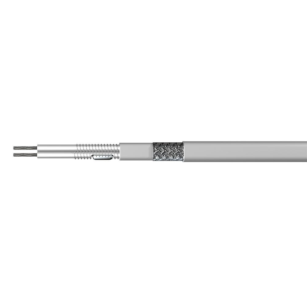
For a facility running mixed conditions — some lines needing simple freeze protection, others holding process temperature above 100°C — it's common to combine cable types rather than force one solution across the whole plant. A flexible constant power heating cable handles longer circuit lengths well, while a constant-wattage three-phase trace heater suits larger industrial loads where single-phase circuits aren't practical.
Matching Control Systems to the Application
Control strategy ranges from a simple line thermostat to a full panel with data logging and remote alarms. Freeze protection circuits often get by with ambient-sensing thermostats that switch the whole circuit on below a set temperature, typically 3–5°C. Process temperature maintenance usually needs closer control, with sensors mounted directly on the pipe and controllers holding a tighter band.
Location changes the requirements too. A control panel installed in a classified hazardous area — common in refineries and chemical plants — needs explosion-proof or intrinsically safe construction, not just a standard enclosure with a higher IP rating. A heating trace control cabinet designed for hazardous locations addresses this directly, with sealed entries and certified components rather than field modifications to a general-purpose panel.
Common Industrial Applications
Electric heat tracing shows up wherever a fluid can't be allowed to freeze, thicken, or drop below a process minimum. The most frequent applications include:
- Freeze protection for outdoor water, fire suppression, and instrument lines in cold climates
- Viscosity control on crude oil, heavy fuel, and asphalt lines where flow stops below a threshold temperature
- Process temperature maintenance in chemical and pharmaceutical manufacturing
- Roof and gutter de-icing on commercial buildings
- Tank heating for storage vessels holding temperature-sensitive liquids
Oil and gas facilities account for a large share of installed capacity, largely because a single frozen line during a cold snap can shut down an entire process train. A properly sized freeze protection high-temperature trace heater costs far less than the downtime it prevents.
Installation and Inspection Best Practices
Cable spacing, attachment method, and insulation sequencing all affect final performance, which is why most specifications reference a recognized standard rather than leaving these details to interpretation. The IEEE standard covering testing, design, installation, and maintenance of electrical resistance trace heating is the document most commonly cited in industrial specifications for this reason.
Before insulation goes on, every circuit should pass a dielectric insulation resistance test — typically at 2500 Vdc for polymer-insulated cable — to confirm there's no damage from installation. Skipping this step is one of the most common causes of early-life failures, since a nicked cable jacket often won't show symptoms until moisture works its way in months later. For a closer look at splice methods, spacing tolerances, and inspection checkpoints, our breakdown of construction techniques and inspection standards for electric heat tracing covers the full sequence in more detail.
Proper termination hardware matters as much as the cable itself. Using trace heater installation kits and accessories rated for the specific cable type avoids the mismatched connectors that account for a large share of post-installation service calls.
Maintenance Tips to Extend System Life
Most heat tracing problems trace back to two causes: damaged or wet insulation, and connection failures at splices or terminations. A visual inspection before calling for service catches a surprising number of issues — insulation that's been walked on, jacketing torn during nearby pipe work, or a junction box left open after maintenance.
Annual megohmmeter testing on each circuit, paired with a check of control panel setpoints, catches degradation before it turns into a frozen line during the first hard freeze. Circuits that trip repeatedly on ground fault protection almost always point to compromised cable insulation rather than a nuisance in the breaker itself, so treat repeated trips as a signal to test the cable, not just reset the panel.

 English
 русский
 Français
 Español
 عربى
عربى
