A 4-inch condensate line, insulated and traced in October, split at a flange in January. The cable itself was fine. The thermostat was sensing air under the cladding instead of pipe temperature, the cable had been spiraled at a spacing one size too wide for the heat loss of that pipe, and the insulation had been opened at three pipe supports during steelwork and never sealed again.
The pattern repeats across plants. Failures in heat trace piping are rarely failures of the heating cable. They are sizing, control and installation decisions made weeks earlier by people who each did their own job correctly but never worked from the same numbers.
The practical conclusion up front: design the cable, the insulation and the control as one system, against one calculated heat loss figure, and then prove the result with measurements at commissioning. Everything below explains why that order matters and what it changes on site.
Start With the Duty, Not With the Cable
Two very different jobs get called the same thing, and confusing them is the most expensive mistake available in the design phase.
- Freeze protection keeps the contents above 0°C with a working margin, usually 3–5°C, through the coldest ambient the site expects. Accuracy is not critical; continuity of heat is.
- Process temperature maintenance holds a defined value, for example 50–60°C on heavy fuel oil or 80°C on a viscous additive, inside a band the process can tolerate.
A third duty hides inside the second one: heat-up. If a line or vessel can start cold and viscous, the trace has to supply the watts to raise the temperature within a stated time, and that load is far higher than steady-state maintenance. A system sized only for maintenance will hold temperature beautifully once warm and fail every cold start.
Freeze protection and process maintenance share hardware but not design logic; sizing one like the other is a common and costly shortcut.
| Design question |
Freeze protection |
Process temperature maintenance |
| Set point |
A few degrees above zero, typically 3–5°C |
A process value, often 40–80°C, held in a narrow band |
| Governing load |
Heat loss at the coldest ambient |
Heat loss plus any heat-up requirement |
| Typical cable |
Self-regulating, low to medium output |
Self-regulating, constant wattage or MI, often higher output |
| Control |
Adjustable thermostat, ambient or line sensing |
Electronic controller with a line RTD and alarm contacts |
| Typical failure |
Cold spots at valves, supports and dead legs |
Overshoot, scorched product, breaker trip on cold start |
| Proof at handover |
Insulation resistance and stabilised current per circuit |
The same, plus a recorded hold test at the set point |
For water lines and small-bore instrument runs, a self-regulating cable on a line-sensing thermostat covers most freeze protection cases. The specification that matters is not the brand on the drum but the output at the pipe temperature you actually expect, taken from the manufacturer's power curve rather than from the headline figure at 10°C.
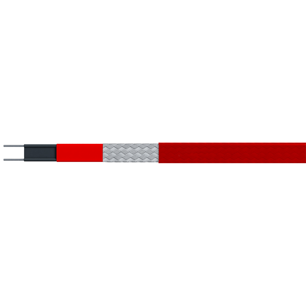 High-Temperature Trace Heater for Freeze ProtectionHigh-temperature trace heating for pipes, tanks, valves and process equipment, using constant-wattage cable for frost protection and temperature maintenance in demanding industrial settings.View Product →
Choose the Cable Family Before the Wattage
Three families cover nearly all industrial piping, and the choice is driven by circuit length, temperature and how much site work you can tolerate.
Circuit length and termination strategy usually decide the cable family before thermal performance does.
| Cable type |
Typical output |
Practical circuit length |
Field cutting |
Best fit |
Watch out for |
| Self-regulating |
Low to medium per metre |
Up to a few hundred metres, limited by breaker size and cold-start current |
Cut to length on site, simple cold lead termination |
Water lines, freeze protection, irregular pipework with many fittings |
Output falls as the pipe warms; check the start-up current, not the running current |
| Constant wattage, single or three phase |
Medium to high per metre |
Long runs, limited mainly by voltage drop |
Resistance-matched sections, less forgiving on site |
Long straight lines and higher maintenance temperatures |
Cannot be overlapped; one damaged section takes the whole circuit down |
| MI / EJMI |
High per metre |
Long, high-temperature circuits |
Factory terminated lengths with longer lead times |
High temperature, steam-adjacent lines, aggressive environments |
Termination quality and cost dominate the project more than cable price |
Three-phase constant wattage is worth a closer look on long headers where a self-regulating cable would need several circuits and several feeders. Fewer, longer circuits mean fewer junction boxes and fewer points of failure in the insulation, which is often the real saving.
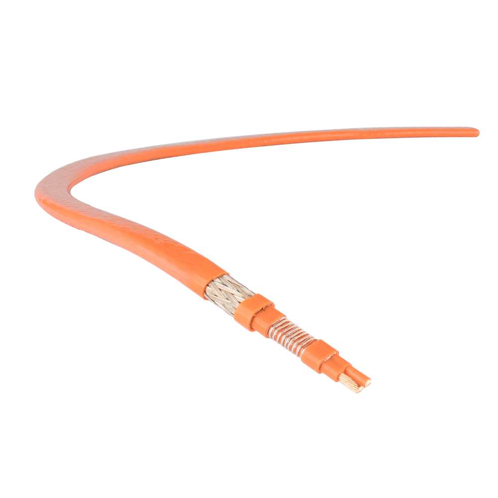 Constant Wattage Three-Phase Trace HeaterThree-phase constant-wattage trace heater for process heating and viscosity control up to 425°C, cut to length on site for long pipeline circuits.View Product →
Heat Loss Is the Number Everything Else Depends On
Every downstream decision — cable output, spiral pitch, thermostat count, breaker size — is a consequence of one figure: the heat loss of the insulated pipe at the design ambient. Calculate it once, in writing, and keep it in the project file.
The calculation itself is not exotic. Loss scales with the temperature difference between the maintained fluid and the coldest ambient, with the pipe surface area, and with the thermal resistance of the insulation build-up. What gets skipped in practice is the correction around it:
- Wind and exposure raise the effective loss on outdoor racks and elevated pipe bridges.
- Supports, valves, flanges and hangers act as thermal bridges; a 10–25% allowance for fittings is normal depending on how many there are.
- Spiral pitch is selected from the manufacturer's tables to match the required watts per metre, not chosen by habit.
- Safety margin of 10–20% is typical, but it should be a documented decision, not a round-up.
As a rough order of magnitude, a well insulated 100 mm water line holding 5°C in a −20°C ambient loses something in the region of 30 W/m; add fittings and wind, and the cable must deliver more than that at the pipe temperature, not at room temperature. That last distinction is where undersized systems come from.
Insulation Work Decides Whether the Cable Ever Earns Its Cost
Running the cable is the quick part. Keeping the heat where it was generated is the part that gets subcontracted and forgotten. A few rules carry most of the benefit:
- Fix the cable against the pipe with glass tape or aluminium foil tape at the manufacturer's recommended spacing, then cover it — never let the cable cross itself or sit on a sharp weld seam.
- On horizontal pipe, run the cable along the lower half where liquid collects, then spiral where the pitch calls for it.
- Fit the sensor on the opposite side of the pipe from the cable, under the insulation, with good thermal contact and its own small cover.
- Close the cladding properly at supports, penetrations and valve stations, and re-seal anything the insulation contractor opened.
- Trace valve bodies, strainers and dead legs, or accept them as designed cold spots and note it in the operating procedure.
Wet insulation is worse than no insulation in freeze protection terms, because it conducts heat away from the pipe and can hide a cable fault behind a plausible temperature reading. Weatherproofing is part of the trace system, not a finishing trade.
Controls, Protection and Power Distribution
Control philosophy is decided at the same table as the cable selection, and it sets the bill of materials for the panel. Ambient-sensing thermostats are cheap and switch on early, but they cannot see the pipe. Line-sensing RTDs with an electronic controller hold a real set point and give you alarms, and they are the only sensible choice where the maintained temperature matters to the product.
On the electrical side, three details are worth writing into the specification: contactors rated with headroom for cold-start current rather than steady-state current, residual current protection suited to the cable type and circuit length, and a circuit schedule that maps every feeder to a physical line, so a fault can be found without opening cladding.
Where the piping runs through a classified area, the control cabinet moves into the same classification as the cable and the junction boxes, with the certification to match.
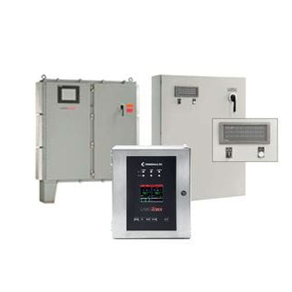 Heating Trace Control Cabinet for Hazardous LocationsControl and monitoring cabinet for heat-tracing systems with 1–72 circuits, supporting temperature control and power management in hazardous-area installations.View Product →
Hazardous Areas Change the Paperwork, Not Just the Hardware
The hardware difference between a general-purpose and a hazardous-area trace system is modest. The documentation difference is not. Zone classification, gas group and temperature class drive the junction box type, the gland selection and the maximum permitted surface temperature of the cable under fault conditions.
For self-regulating cable this means a stabilised design approach: the temperature class is established from the worst-case combination of applied voltage and the highest expected ambient, because the cable's self-limiting behaviour is not a guarantee on its own. Getting this wrong is not detected at commissioning, only at audit. Manufacturer certificates for the cable, the components and the panel belong in the handover pack, and exporters should confirm which schemes the supplier can actually document.
Suppliers that hold third-party certification for their trace and control products, such as the schemes listed on the company's qualification records, are generally easier to qualify in a project with a formal vendor review.
Commissioning Checks That Pay for Themselves
Testing before insulation goes on costs an hour per circuit. Finding the same fault in February costs a shift, a scaffold and a production interruption.
- Record insulation resistance for every circuit before installation, after installation and after insulation is closed.
- Measure conductor resistance or circuit continuity and compare it to the design value; a reading outside tolerance usually means a damaged section or a wrong length.
- Confirm cable, cold lead, gland and junction box match the area classification on the drawing.
- Verify sensor placement and controller parameters against the design set point, including alarm and high-limit settings.
- Energise and record stabilised current and pipe temperature after a defined period, then compare with the calculated values.
- Photograph cable routing, labels and terminations before cladding is replaced; this becomes the maintenance baseline.
Installation practice varies more than product datasheets do, so it helps to align site work with recognised construction and inspection standards for electric heat tracing rather than leaving it to individual habit — the checks described in these construction and inspection notes are a reasonable starting point for a project-specific checklist.
A Short Specification Checklist
Most procurement problems on trace projects come from an inquiry that describes the pipe but not the duty. Including these items in the request shortens the technical review for everyone:
- Pipe size, material, length and layout, including branches, dead legs and valves.
- Maintained temperature with tolerance, and the minimum design ambient with wind exposure.
- Insulation type, thickness and condition, plus who is responsible for closing it.
- Area classification, gas group and required temperature class.
- Supply voltage, phases and available breaker capacity per circuit.
- Control philosophy: thermostat or controller, ambient or line sensing, alarm and remote signalling.
- Acceptance evidence: test sheets, certificates and as-built circuit schedule.
- Installation kits, accessories and spare cable for future repairs.
A line that survives its first winter is not the one with the most cable wrapped around it. It is the one where heat loss, insulation quality, cable output at temperature and control set point were agreed by one responsible engineer before the purchase order went out, and then verified with a meter before the cladding closed over the work. Get those four numbers aligned, and the trace system becomes the least interesting equipment on the site — which is exactly what it should be.

 English
 русский
 Français
 Español
 عربى

