A tank farm adds self-regulating heat trace to a 6-inch caustic line, sets the thermostat to 15 °C, and treats the freeze risk as solved. Two winters later the line plugs during a cold snap, and the panel never alarms. The cable is healthy. The problem is the measurement: the sensor was strapped to the warm side of the pipe, opposite the heating cable, at a point that stayed several degrees above the coldest part of the run.
Heat trace monitoring is not a switch that turns power on and off. It is a measurement system, and it only earns its cost when the temperature, current, and insulation data it collects represent the worst point of the circuit. Everything below follows from that idea: choose the parameters, place the sensors where a failure will actually appear, and decide in advance which signals trip a circuit and which only raise an alarm.
What Heat Trace Monitoring Has to Prove
A working monitoring package answers three questions for every traced circuit: is the pipe at or above its minimum temperature, is the heating cable delivering the power it was designed to deliver, and is the cable insulation still intact. A capillary thermostat answers only the first question, at one point, with no record of what happened overnight. Industrial panels sense considerably more, and the parameters below are the ones worth wiring.
Table 1: The six signals industrial heat trace panels normally monitor, and what each one reveals.
| Parameter |
How it is sensed |
What a change tells you |
| Pipe temperature |
RTD strapped to the pipe wall beneath the insulation |
Direct answer to the freeze or viscosity question at that point of the line |
| Ambient temperature |
RTD, or a sensor built into the controller |
Sets the control band on self-regulating circuits; a wrong ambient reading shifts output without raising any alarm |
| Circuit current |
Current transformer or shunt, one per branch |
Separates a cable fault from a control fault; a cable cut at a support shows up here long before the pipe cools |
| Ground-fault leakage |
Ground-fault sensing on each branch |
Earliest warning of moisture in a junction box or a damaged jacket; a slow upward trend usually precedes a trip |
| Supply and breaker status |
Auxiliary contacts and voltage sensing |
Distinguishes "no heat because no power" from "no heat because the cable failed" |
| Insulation resistance |
Megohmmeter test at commissioning and at shutdowns |
Provides a baseline so gradual cable degradation becomes visible instead of sudden |
On a short freeze-protection run, a thermostat per circuit may be all that is justified. On a plant with analyzer sample lines, solvent transfer piping, and a loading arm, per-circuit current and ground-fault sensing pay for themselves the first time a cable is cut behind closed insulation, because a temperature alarm alone says a pipe is cold without saying why.
Three Monitoring Architectures and What Each One Cannot See
Monitoring is often presented as a feature, but it is really a choice of architecture. The three common levels differ less in the temperature they read than in the number of faults they can actually name.
Table 2: Three monitoring architectures compared by the faults each one is able to identify.
| Architecture |
Signals available |
Where it fits |
Main limitation |
| Mechanical thermostat with remote bulb |
Pipe temperature only |
Short freeze-protection circuits with no need for remote indication |
No current, no ground fault, no history; a welded contact looks exactly like a healthy circuit |
| Local panel with contactors, thermostats, and lamps |
Temperature, breaker status, lamp indication |
Single buildings and small plants where an operator passes the panel daily |
Alarms exist only at the panel; no trending and no remote notification |
| Multi-circuit controller or PLC with plant network link |
Per-circuit temperature, current, ground-fault leakage, timestamped alarms |
Larger sites, remote or unmanned locations, classified areas |
Higher engineering effort; needs a point list, alarm rationalisation, and someone to review trends |
The step from the first level to the second is about detecting a fault at all. The step from the second to the third is about detecting a fault before the pipe goes cold, because current and leakage data on a self-regulating circuit change well before the temperature reading moves.
Where the panel itself sits in an explosive atmosphere, the enclosure becomes part of the monitored system rather than a container for it. A certified assembly keeps per-circuit sensing, switching, and isolation inside one housing.
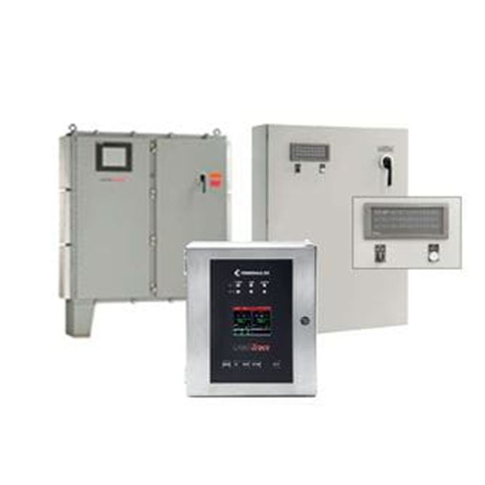 Heating Trace Control Cabinet for Hazardous LocationsA control and monitoring cabinet for heat tracing systems, supporting up to 72 circuits and integrating temperature control, detection, and power management in hazardous areas.View Product →
Sensor Placement and Wiring Decide Whether the Data Is Trustworthy
The sensor belongs at the coldest point
The working rule in trace heating is to place the sensor in the most extreme location, meaning the point with the lowest expected temperature. In practice that is the downstream end of a long run, the pipe upstream of a control valve where the medium is still cold, the bottom of a vertical riser, or a section where insulation is thinner or wind exposure is higher. If a single circuit covers more than one such point, use two or three sensors and let the controller act on the lowest reading instead of accepting one sample as a survey.
Contact quality matters as much as location. The sensing tip must touch the pipe wall, never the heating cable jacket, which runs tens of degrees hotter. Strap it with a stainless band or aluminium foil tape so it cannot slide during thermal cycling, and re-insulate over the sensor to the same thickness as the rest of the line. Run the lead with a drip loop and keep the termination head clear of water that pools along the insulation cladding. Accessories chosen for this purpose, including straps, termination kits, and junction hardware, are usually specified at the same time as the cable rather than added on site.
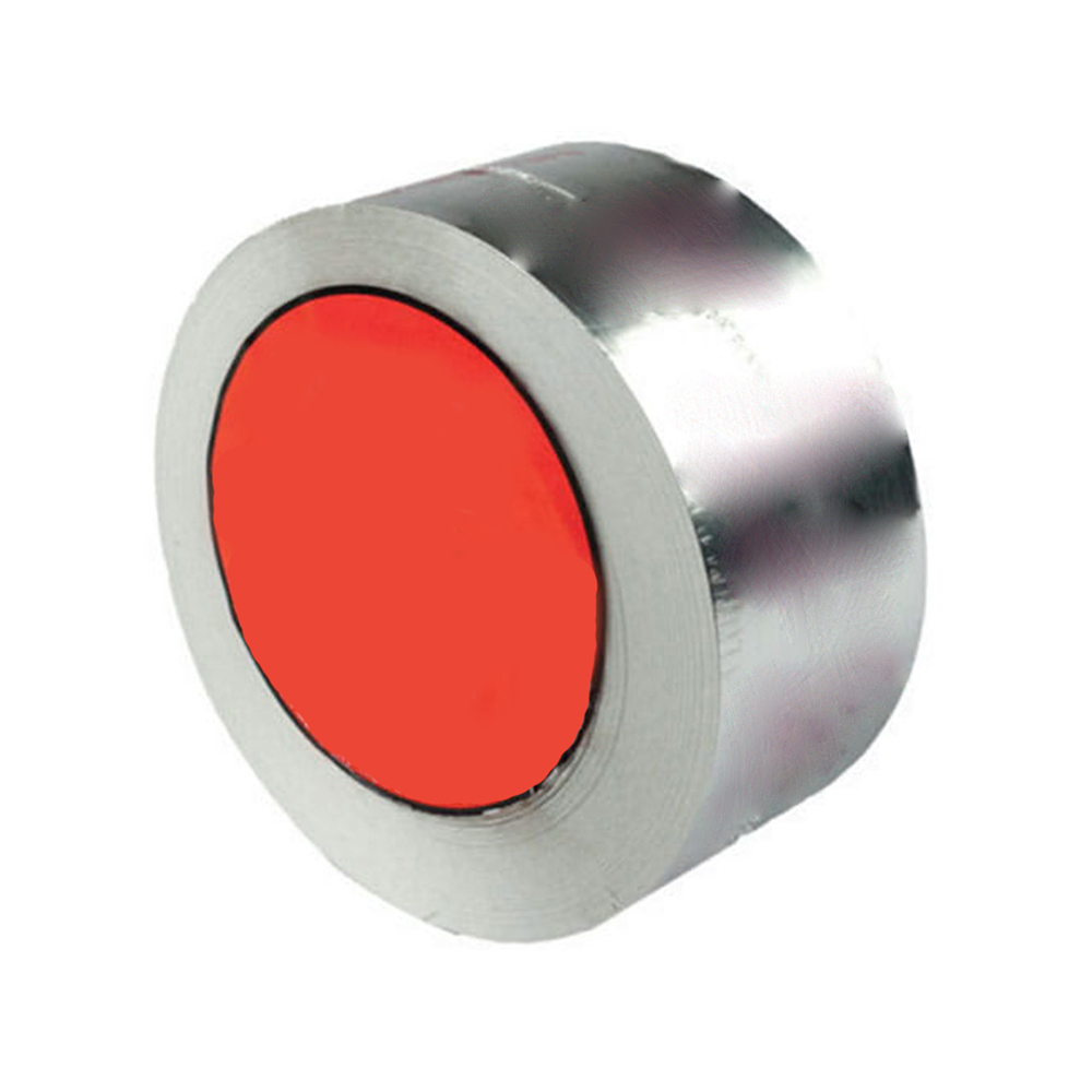 Trace Heater Installation Kits and AccessoriesInstallation components including splices, connection boxes, end seals, tapes, straps, and ambient or line sensing RTDs for reliable heat trace cable mounting and termination.View Product →
RTD or thermocouple
For set points between roughly 5 and 60 °C, a PT100 or PT1000 resistance sensor is the safer default. Tolerance classes keep the error inside a degree or two, and a three-wire connection cancels the resistance of the lead itself, which matters when the sensor sits thirty metres from the panel. Thermocouples cost less and tolerate higher temperatures, but they add cold-junction error and need compensating cable. When the alarm band between set point and minimum allowable temperature is only 5 to 10 °C wide, two or three degrees of measurement error consumes a large share of the available margin.
Wiring detail that prevents nuisance alarms
Route RTD signal cable away from contactor feeds and motor circuits, earth the shield at the panel end only, and keep a consistent reference for every sensor on the same controller. Most "sensor faults" reported in the first months of operation turn out to be a loose ferrule or a shield bonded at both ends, not a failed element.
Which Alarms Should Trip the Circuit and Which Should Only Inform
Every set point is a decision about downtime, so it helps to sort alarms into three groups before the panel is built.
- Trip immediately: ground-fault leakage above the protection threshold, overcurrent on a constant-wattage or MI branch, and high pipe temperature on lines carrying temperature-sensitive media.
- Annunciate with a delay: low pipe temperature, typically held off for 30 to 60 minutes after a restart so a cold line coming up to set point does not flood the alarm list.
- Trend rather than alarm: current deviation within about 15 percent of the design value, and insulation-resistance readings that drift downward between shutdowns. These are the signals that let maintenance schedule a repair instead of reacting to one.
Delays and deadbands are not cosmetic. Self-regulating cable draws a high inrush current when cold, so a current alarm without a short start delay will operate every time a circuit energises after a weekend shutdown, and operators soon learn to ignore it.
Commissioning and Routine Audits
Monitoring only earns its keep if the data is verified at handover and checked on a schedule. A practical audit works through the same items each time.
- Compare each circuit's temperature reading against an independent contact thermometer at the sensor location.
- Record measured current per circuit at operating temperature and file it as the baseline for future comparison.
- Confirm that panel labels, drawings, and physical circuits match, including changes made during construction.
- Trigger each alarm class deliberately, by opening an RTD, shifting a set point, or simulating a ground fault, and confirm the annunciation reaches the right place.
- Inspect insulation at valves, supports, and flanges; wet or missing insulation is the most common single cause of both heat loss and ground-fault leakage.
- Log insulation-resistance readings at each shutdown so a downward trend becomes visible before a trip.
- Check that hazardous-area terminations, glands, and seals still match the certification of the enclosure.
Most of these checks are mechanical rather than electronic, and the field details that decide whether a traced line holds temperature in service are covered in our notes on construction techniques and inspection standards for electric heat tracing.
Matching the Monitoring Package to the Heating Cable Type
The cable technology changes what a "normal" reading looks like, and the monitoring logic should be written accordingly.
- Self-regulating cable: output falls as pipe temperature rises, and cold-start current can be several times the steady value, so current alarms need a start delay and a generous deadband.
- Constant-wattage cable: output is fixed, so measured current should stay close to the design value at all times, which makes this the easiest technology to monitor closely.
- Mineral-insulated and series-resistance cable: used for high-temperature or very long single runs, where ground-fault sensing and insulation-resistance records matter more than fast current alarms, because damage hides under a metal sheath.
Monitoring hardware should be selected alongside the cable, not afterwards. A three-phase constant-wattage circuit, for example, needs three-phase current sensing and balanced-load logic rather than a single-phase current transformer sized for a different load.
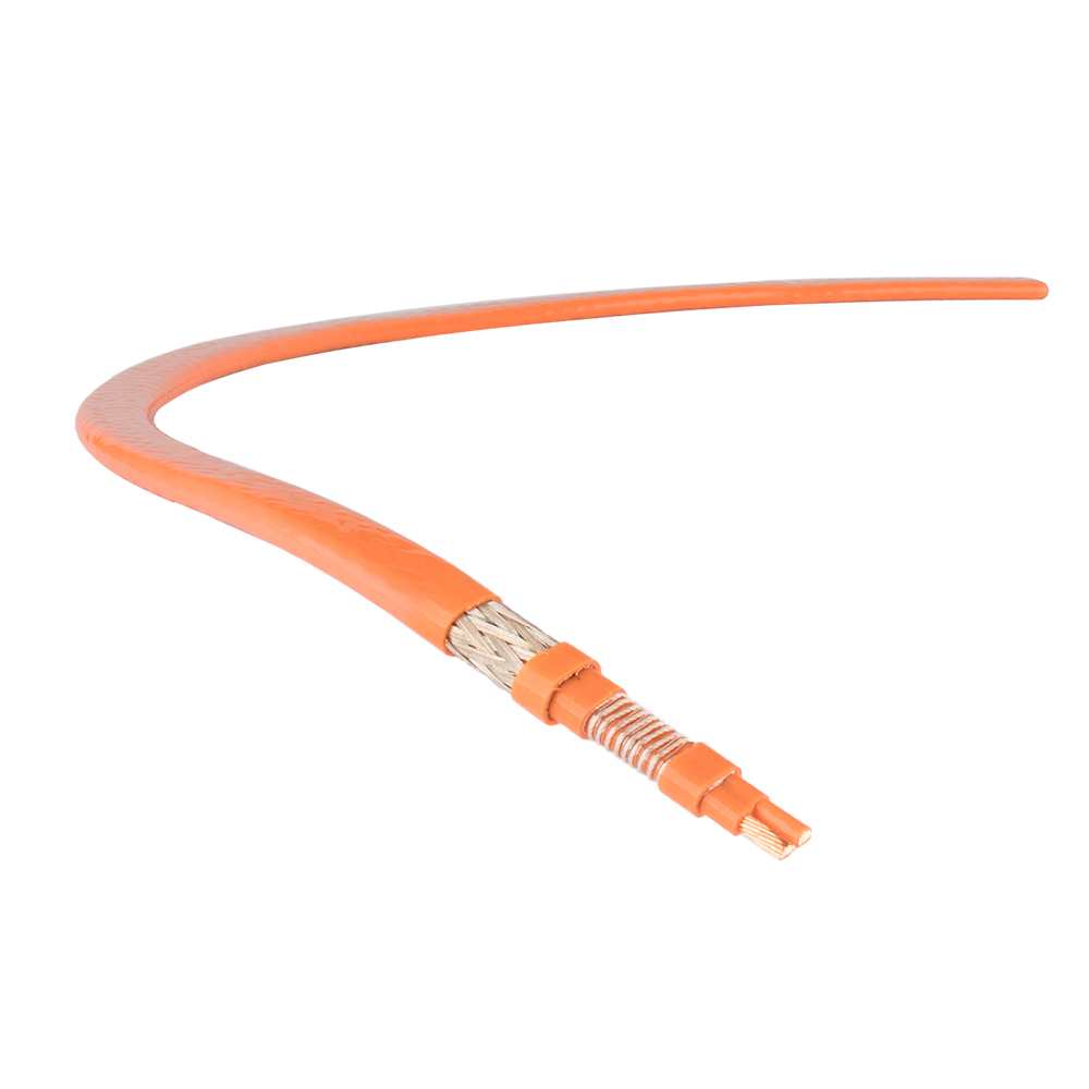 Constant Wattage Three-Phase Trace HeaterA three-phase constant-wattage heat trace heater for process heating and viscous flow control, cut to length and suitable for demanding, corrosive high-temperature applications.View Product →
What to Write Into the Specification
A short list of requirements removes most ambiguity at the quotation stage.
- One temperature sensor per circuit, with its location marked on the line isometric.
- Current and ground-fault sensing on every branch, not merely on the panel feeder.
- Alarm set points, deadbands, and time delays issued as a schedule rather than left to the panel builder.
- Communication protocol and point list for the plant control system.
- Certification of the enclosure for the area classification, quoted with certificate numbers.
- As-built drawings, set point schedule, and test records handed over at completion.
None of this is exotic engineering, and none of it is expensive relative to the cost of a blocked line or a spoiled batch. For freeze protection in a cold climate or viscosity control on a heavy oil header, the difference between a monitored system and an unmonitored one shows up as avoided downtime. Our heat trace range covers constant-wattage, self-regulating, and high-temperature cables together with the panels, sensors, and accessories that make the measurements meaningful, and the engineering team can review a line list with you to agree the sensor locations before anything is ordered.

 English
 русский
 Français
 Español
 عربى

