What Heat Trace Installation Actually Involves
Heat trace installation is the process of applying electrical resistance heating cable to pipes, vessels, valves, instruments, or structural surfaces to prevent freezing, maintain process temperatures, or compensate for heat loss to the surrounding environment. The concept is straightforward: run a heating cable in close contact with the surface that needs to be protected, insulate over the top to retain the generated heat, connect to a power supply and control system, and the surface stays within the required temperature range regardless of ambient conditions.
What makes installation the critical variable in system performance is the gap between concept and execution. Poor installation accounts for the majority of heat tracing failures in both industrial and commercial settings — not cable defects, not control system errors, not design miscalculations. Cables damaged during routing, terminations that allow moisture ingress, insulation applied before cable testing, thermostats positioned incorrectly, and bend radii exceeded during installation are each capable of producing a system that fails exactly when it is needed most: during the coldest period of the year.
Understanding heat trace installation as a disciplined, sequential process — not a straightforward wiring job — is the foundation of reliable long-term system performance. This applies equally to a short domestic pipe freeze protection run and a complex multi-circuit industrial process temperature maintenance installation on a chemical plant.
Selecting the Right Cable Type Before Installation Begins
The single most consequential installation decision is made before a single length of cable is unrolled: selecting the correct cable type for the application. Installing the wrong cable type cannot be corrected by careful workmanship — it is a fundamental specification error that compromises the system regardless of how precisely the cable is subsequently applied.
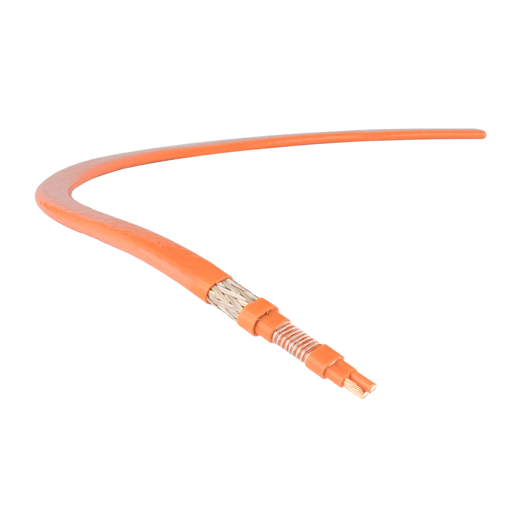
Self-regulating cables use a conductive polymer core that automatically increases electrical resistance — and therefore reduces heat output — as the cable temperature rises, and decreases resistance as temperature falls. This behavior means the cable adjusts its output independently at every point along its length, making it inherently safe against overheating and energy-efficient in variable ambient conditions. For a detailed understanding of how this technology works and where it excels, self-regulating heat tracing is the dominant choice for freeze protection of water pipes, general process temperature maintenance up to approximately 65°C, roof and gutter de-icing, and most commercial and light industrial applications.
Parallel constant wattage cables deliver a fixed power output per unit length regardless of temperature, making them suitable for longer circuit runs and higher maintain temperatures than self-regulating designs allow. Because they do not self-limit, they require thermostat control to prevent overheating — a design requirement that must be accounted for in both the installation and the control system specification. They are widely used for viscous fluid lines, tank heating, and process temperature maintenance above the self-regulating range.
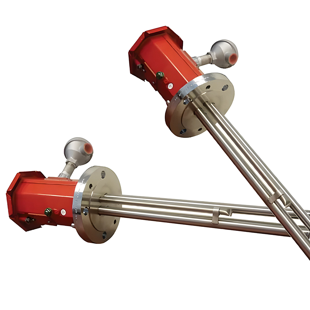
Mineral insulated (MI) cables consist of metal conductors embedded in compacted magnesium oxide insulation inside a stainless steel or alloy sheath. They withstand continuous operating temperatures above 350°C and exposure temperatures exceeding 500°C, making them the specification choice when temperature or power output requirements exceed the capability of polymer-insulated cables. MI cables are factory-terminated rather than field-spliced, which imposes precise length determination requirements during the design phase but eliminates the most common source of installation-related moisture ingress failures.
Mismatching cable type to application — most commonly using a low-temperature self-regulating cable in a high-temperature process application, or specifying a constant wattage cable without adequate temperature control — results in either cable degradation over time or inadequate temperature maintenance. Consulting the manufacturer's specification data and, where required, performing a formal design calculation before procurement prevents these errors. Further guidance on matching cable type to application requirements is available in our trace heater types and selection reference.
Pre-Installation Planning: Heat Loss Calculations and Circuit Design
Before cable is purchased or installation begins, the system must be designed around a heat loss calculation that establishes how much power is needed to maintain the target pipe or surface temperature under the worst-case ambient conditions at the installation site.
The fundamental heat loss calculation for an insulated pipe accounts for pipe diameter, the thermal conductivity (lambda value) of the insulation material, insulation thickness, the minimum design ambient temperature, and the target maintenance temperature. The resulting figure — expressed in watts per meter of pipe — establishes the minimum output rating required from the heating cable. Safety factors, typically 10–25% above the calculated minimum, are applied to account for variations in insulation quality, wind chill effects on exposed surfaces, and heat losses at valves, flanges, and pipe supports that exceed the losses along straight pipe runs.
Circuit design follows from the heat loss calculation. Maximum circuit length is constrained by the voltage drop across the cable at the supply voltage — exceeding the rated maximum circuit length results in reduced output at the far end of the circuit and inadequate temperature maintenance. For parallel constant wattage and self-regulating cables, maximum circuit lengths are published in the manufacturer's product data and depend on cable wattage rating, supply voltage, and ambient temperature. Long pipeline runs that exceed single-circuit limits require multiple circuits fed from intermediate junction boxes, with each circuit separately protected and monitored.
Power supply and circuit protection sizing are determined at this stage, not during installation. Ground fault protection devices (GFPDs) are required on heat tracing circuits in most electrical code jurisdictions to provide personnel protection against ground faults in wet or corrosive environments. The trip rating of the GFPD — typically 30 mA for personnel protection — must be compatible with the normal ground leakage current of the installed cable length; excessively long circuits can produce leakage currents that cause nuisance tripping of correctly rated GFPDs.
Step-by-Step Installation: Surface Prep, Routing, and Fixing
With design complete and materials confirmed, installation follows a defined sequence that should not be abbreviated or reordered.
Surface preparation is the first physical step. The pipe or vessel surface must be clean, dry, and free of sharp edges, weld spatter, burrs, or corrosion that could damage the cable jacket during routing or under thermal cycling. Any existing insulation or cladding that will be removed and replaced must be taken off before cable application begins. Surfaces that have been treated with certain coatings or paints require compatibility verification with the cable jacket material — some solvents and coatings degrade fluoropolymer or polyolefin jackets over time.
Cable routing position on the pipe determines heat transfer efficiency and long-term cable integrity. For a single cable run on a straight pipe, the 4 o'clock or 5 o'clock position — slightly below the horizontal centreline — is the standard placement. This position ensures the cable is pressed against the pipe by gravity rather than hanging free on the underside, maximizes contact area with the pipe surface, and allows condensation and process fluids to drain away from the cable rather than pooling around it. For larger pipes requiring higher wattage than a single cable provides, spiral wrapping or multiple parallel runs are applied according to the design specification, using an attachment spacing that maintains consistent contact without compressing the cable.
Cable attachment at regular intervals — typically every 300 mm on straight runs — uses aluminum adhesive tape, glass filament tape, or cable ties rated for the installation temperature range. Aluminum tape provides the dual benefit of mechanical attachment and improved thermal contact between the cable and pipe surface, reducing the effective thermal resistance between heat source and pipe wall. At valves, flanges, pumps, and pipe supports, additional cable length is looped around the fitting according to the manufacturer's allowance tables — these components represent localized heat sinks that require proportionally more cable to compensate for their additional thermal mass.
Thermal insulation is applied over the completed cable installation, not before. Insulating over the cable without testing it first is one of the most costly installation errors possible, since any fault discovered after insulation is installed requires full removal and replacement of the cladding system.
Power Connections, Thermostats, and Control Systems
Electrical connections are the most failure-prone elements of any heat trace installation and deserve correspondingly careful attention during both installation and subsequent inspection.
The power connection — where the supply cable joins the heating cable — is made inside a rated junction box appropriate to the area classification. In non-hazardous areas, standard weatherproof boxes are acceptable. In areas classified as hazardous under NEC, IECEx, or ATEX standards, explosion-proof or increased-safety rated enclosures are mandatory, and the cable entry fittings must maintain the integrity of the enclosure's protection concept. All conduit entries must be sealed to prevent condensate from entering the junction box — moisture in power connection boxes is a leading cause of insulation resistance degradation over time.
The end termination is equally critical. The open end of the heating cable must be sealed against moisture ingress using a heat-shrink end seal kit. An unterminated or poorly sealed end allows water to wick into the cable core through capillary action, degrading insulation resistance progressively until the circuit trips or fails. End seal installation should be performed with the cable end dry and clean, following the manufacturer's kit-specific instructions precisely — shortcuts in end sealing are a disproportionate source of field failures.
Thermostat and controller placement determines whether the control system accurately represents the temperature condition it is managing. A pipe-sensing thermostat must be clamped directly to the pipe surface, positioned between the heating cable and the pipe rather than between the cable and the insulation — if mounted on top of the cable, it measures cable surface temperature rather than pipe temperature and will cycle the system incorrectly. Ambient-sensing thermostats should be positioned in a location representative of the coldest expected ambient condition at the installation, shielded from direct solar radiation and heat sources that would cause artificially high readings.
Modern electronic controllers offer significant advantages over simple mechanical thermostats for complex installations: programmable setpoints, alarm outputs for high or low temperature deviations, ground fault monitoring, and data logging capability for maintenance records and regulatory compliance. For critical process lines, ground fault monitoring that reports faults without tripping the circuit — allowing continued operation while maintenance is arranged — is a valuable operational feature.
Testing and Commissioning: IR Test and Continuity Checks
No heat trace installation should be energized for the first time without completing a structured commissioning test sequence. Testing serves two purposes: confirming that the installation is electrically sound before thermal insulation is applied (when repairs are still straightforward), and establishing a baseline measurement record against which future maintenance tests can be compared.
The insulation resistance (IR) test is the primary installation quality check. Using a calibrated megohmmeter, the resistance between the heating cable conductors and the metallic braid or ground is measured at a specified test voltage — typically 500 Vdc or 1,000 Vdc depending on the cable rating. A minimum value of 20 MΩ is the accepted threshold for a successful installation; values below this indicate moisture ingress, jacket damage, or an incorrectly made termination that must be identified and corrected before the circuit is energized or insulated.
IR testing should be performed at three stages: on receipt of cable before installation (to confirm the cable was not damaged in transit), after cable installation and before thermal insulation application (to confirm no damage occurred during routing and fixing), and after thermal insulation is complete (as the final pre-commissioning check). Comparing the three sets of readings identifies at which installation stage any degradation occurred, directing remediation efficiently.
The continuity check confirms that the heating circuit is complete — that the cable conductors are connected end-to-end without open circuits. For self-regulating and parallel constant wattage cables, continuity is confirmed by measuring resistance across the circuit at ambient temperature and comparing the result against the manufacturer's published resistance data for the installed cable length and temperature. A reading significantly higher than expected indicates an open circuit or a high-resistance joint; a reading significantly lower may indicate a short circuit or cable-over-cable contact point generating localized overheating.
Once IR and continuity tests are satisfactory, the circuit is energized and monitored for correct operation. Pipe surface temperatures at the thermostat location and at several points along the circuit are measured after sufficient warm-up time to confirm that the cable is delivering the specified output and that the control system is cycling correctly. All test results, cable lengths, circuit breaker assignments, and thermostat settings are documented in an installation report — a record that supports future maintenance, insurance requirements, and regulatory inspection.
Common Installation Mistakes and How to Prevent Them
Experience across industrial and commercial heat trace installations consistently identifies a small number of errors that account for a disproportionate share of system failures. Awareness of these failure modes is the most effective preventive measure.
Exceeding the minimum bend radius is among the most common cable damage mechanisms. Every heating cable has a specified minimum bend radius — typically six to eight times the cable diameter for self-regulating types — below which the internal conductors or polymer core are mechanically stressed. Forcing cable around tight corners, valve bodies, or pipe supports at radii below the specification creates localized damage that may not be apparent immediately but causes accelerated insulation degradation and eventual ground faults under thermal cycling. Using the correct fitting allowance tables and taking additional time to route cables smoothly around obstructions eliminates this risk.
Cable-on-cable overlap is particularly hazardous for constant wattage and self-regulating cables in high-temperature applications. Where two sections of cable cross or run parallel without separation, the overlapping point receives heat from both cables simultaneously. Self-regulating cables partially compensate by reducing output as temperature rises, but constant wattage cables do not — the overlap point can reach temperatures that damage the cable jacket and, in extreme cases, ignite adjacent insulation materials. Cable routing plans that identify and eliminate potential overlap points before installation begins are the correct preventive approach.
Inadequate end sealing remains the leading cause of insulation resistance failure in field installations. End seal kits require clean, dry cable ends, careful heat application to fully activate the heat-shrink components, and sufficient cooling time before the sealed end is exposed to moisture. Rushed end sealing — particularly in cold or wet outdoor conditions — produces seals that appear intact visually but allow moisture ingress under pressure cycling, leading to progressive IR degradation over months to years.
Insulating before testing converts a manageable installation defect into a costly remediation project. The rule is simple and non-negotiable: complete the IR test and continuity check, confirm both results are within specification, then apply thermal insulation. Any sequence that inverts this order creates an avoidable risk that the installation team and the system owner will both regret when a fault is subsequently discovered beneath finished cladding.
Incorrectly sized circuit breakers cause nuisance tripping on cold mornings — precisely when the heat trace system is most needed. Self-regulating cables exhibit high inrush current at low startup temperatures, sometimes two to three times their steady-state current draw. Circuit breakers must be sized to accommodate this inrush without tripping, using the manufacturer's published cold-start current data rather than the steady-state wattage alone. Undersized breakers that trip on startup leave pipes unprotected and generate unnecessary service calls that are entirely avoidable through correct specification at the design stage.
 English
 русский
 Français
 Español
 عربى
عربى