Trace Heaters Prevent Freeze Damage and Maintain Flow — When Installed Correctly
A trace heater is a resistive heating cable or tape applied along the length of a pipe, vessel, or instrument to prevent freezing, maintain process temperatures, or compensate for heat loss. Proper heat trace installation is the single most important factor determining whether a system performs reliably or fails prematurely — poor installation accounts for the majority of heat tracing failures in industrial and commercial settings.
Whether you're protecting a residential water supply line in a cold climate or maintaining viscous fluid flow in a chemical processing plant, trace heaters offer a proven, energy-efficient solution. This guide covers the practical details: types of trace heaters, how to select the right one, and how to complete a heat trace installation that meets both performance requirements and safety codes.
How a Trace Heater Works
A trace heater works by converting electrical energy into heat along its entire length, transferring that heat conductively to the surface it contacts. The heater runs parallel to or spirally around the pipe, and thermal insulation is applied over both to retain the generated heat and improve efficiency.
The amount of heat output required depends on three variables: the minimum ambient temperature the system must withstand, the target pipe or fluid maintenance temperature, and the thermal conductivity of the insulation used. A typical freeze-protection application for a water pipe might require 5–10 watts per meter (W/m), while a high-temperature process maintenance application for heavy fuel oil could demand 30–80 W/m or more.
Most modern trace heaters are connected to a thermostat or electronic control unit that monitors ambient or pipe temperature and switches the heater on or off as needed, reducing energy consumption by 30–70% compared to continuously powered systems.
Types of Trace Heaters and When to Use Each
Choosing the wrong heater type leads to energy waste, overheating risk, or inadequate protection. The four primary types differ significantly in their self-regulation behavior, temperature range, and application suitability.
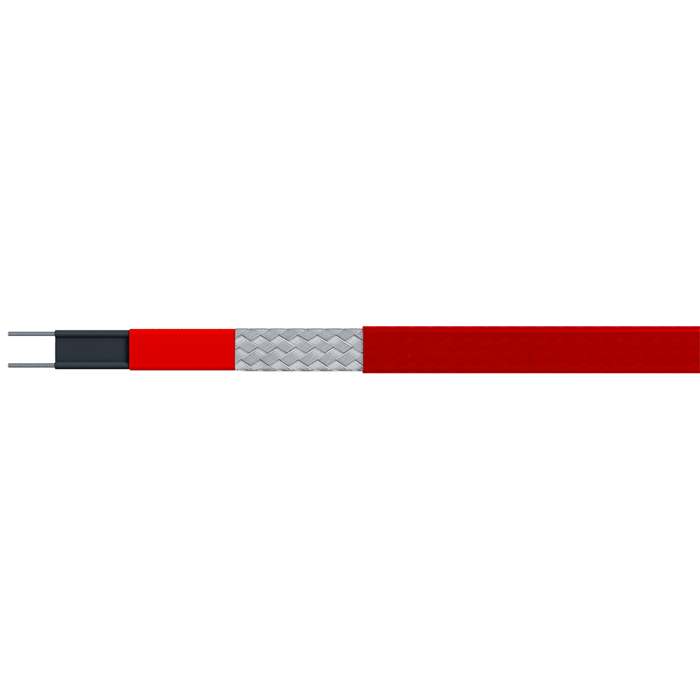
Self-Regulating (Self-Limiting) Trace Heaters
Self-regulating cables contain a conductive polymer core between two bus wires. As temperature rises, the polymer's electrical resistance increases, automatically reducing heat output. As temperature drops, resistance falls and output increases. This behavior makes them the safest and most versatile option for most installations.
- Can be cut to any length on site without rewiring
- Cannot overheat even if overlapped or crossed
- Typical output range: 5–33 W/m at 10°C
- Maximum exposure temperature: 65°C (standard) or 85°C (high-temperature grade)
- Best for: freeze protection of water pipes, roof/gutter de-icing, general process temperature maintenance
Constant Wattage Trace Heaters
Constant wattage cables deliver a fixed output regardless of temperature. They are available in two configurations: series resistance (a single continuous resistance element) and parallel resistance (heating elements connected in parallel zones). Parallel constant wattage cables can be cut to specific lengths; series types cannot.
- Precise, predictable heat output — ideal for engineered process systems
- Risk of overheating if thermostatic control fails — requires reliable control systems
- Typical output: 8–95 W/m depending on circuit design
- Best for: long pipeline runs, industrial process temperature maintenance, viscous fluid heating
Mineral-Insulated (MI) Trace Heaters
MI heaters consist of a resistance wire surrounded by compressed magnesium oxide insulation inside a metal sheath. They are rated for extreme temperatures — up to 650°C surface temperature in some configurations — and are mechanically robust enough for harsh industrial environments.
- Highly durable; resistant to mechanical damage, chemicals, and moisture
- Must be factory-fabricated to exact length — not field-trimmable
- Higher upfront cost but longest service life
- Best for: steam tracing replacement, high-temperature process applications, hazardous area installations
Skin-Effect Trace Heaters
Skin-effect systems use a ferromagnetic outer pipe as part of the heating circuit, generating heat through the skin effect of AC current. They are designed specifically for very long pipeline runs — typically 5 km to 25 km — making them common in oil and gas pipeline applications where conventional cable systems would be impractical.
| Type |
Self-Regulating |
Max Temp |
Field-Trimmable |
Typical Application |
| Self-Regulating |
Yes |
85°C |
Yes |
Freeze protection, general maintenance |
| Constant Wattage (Parallel) |
No |
120°C |
Yes |
Industrial process lines |
| Mineral-Insulated |
No |
650°C |
No |
High-temp / hazardous areas |
| Skin-Effect |
No |
150°C+ |
No |
Long-distance oil/gas pipelines |
Comparison of trace heater types by key technical characteristics and application
Heat Trace Installation: Step-by-Step Process
A heat trace installation that fails inspection or underperforms in winter is almost always the result of skipping key preparation steps or misapplying the cable. The following process applies to a standard self-regulating or parallel constant wattage installation on metallic or plastic piping — the most common scenario for both commercial and industrial use.
Step 1 — Design and Load Calculation
Before purchasing cable, calculate the heat load required. The standard formula accounts for pipe diameter, insulation thickness, insulation thermal conductivity (lambda value), minimum ambient temperature, and target maintenance temperature. Most major manufacturers (Raychem/nVent, Thermon, BriskHeat) provide free design software that generates a W/m requirement and recommends cable models automatically.
As a practical reference: a 2-inch (50 mm) steel pipe requiring freeze protection at −20°C with 50 mm of mineral wool insulation typically needs approximately 10–15 W/m of trace heater output. Without insulation, the same pipe may require 40–60 W/m — illustrating why insulation is always installed over heat trace, never omitted.
Step 2 — Surface Preparation
Clean the pipe surface of rust, scale, oil, and debris. On metallic pipes, the trace heater must make direct contact with bare metal for optimal heat transfer. On plastic pipes, aluminum foil tape is applied first as a thermal spreader — this is a step frequently missed on plastic pipe jobs and results in hot spots and uneven temperature distribution.
Step 3 — Cable Routing and Attachment
Route the cable along the bottom of horizontal pipes (the 5 o'clock or 7 o'clock position) to ensure it remains in contact if condensation or ice forms. On vertical pipes, run the cable straight. Secure the cable every 300 mm (12 inches) using fiberglass or aluminum adhesive tape — never standard PVC tape, which degrades under heat cycling.
At valves, flanges, pumps, and pipe supports, add extra cable length as a loop or spiral to compensate for the higher heat loss at these fittings. A standard valve typically requires an additional 0.5–1.5 meters of cable depending on valve size. Manufacturer installation guides provide fitting allowance tables for precise calculations.
Step 4 — End Seal and Power Connection
The free end of the cable must be sealed with a manufacturer-supplied end seal kit to prevent moisture ingress into the cable core. Failure to properly seal the cable end is one of the most common causes of insulation resistance failure and ground fault trips. Apply the end seal before the cable is energized and before insulation is installed.
The power connection end is terminated in a suitable junction box — rated for the environment (e.g., IP65 for outdoor, ATEX/IECEx-certified for hazardous areas). For 120V or 240V systems, a dedicated circuit with a GFCI (Ground Fault Circuit Interrupter) breaker rated at 30 mA is required by most electrical codes, including NEC Article 427 in the United States.
Step 5 — Insulation Installation
Install pipe insulation — typically mineral wool, calcium silicate, or cellular glass depending on the process temperature — over the traced pipe immediately after all electrical connections are completed and tested. The insulation jacket (aluminum or PVC cladding) is applied last to protect against weather and mechanical damage.
Leave a labeled inspection window or access point at the power connection junction box and at any thermostat sensor locations. Burying these points under insulation — a common shortcut — makes future maintenance and fault diagnosis significantly harder.
Step 6 — Testing and Commissioning
Before energizing, perform an insulation resistance (IR) test using a 500V or 1000V megohmmeter. A healthy self-regulating cable should read greater than 20 MΩ between the conductors and the braid/earth screen. Values below 1 MΩ indicate moisture ingress or damage and must be investigated before the system is commissioned.
After energizing, measure the current draw and compare against the manufacturer's rated current at the installation ambient temperature. Log all test results in an as-built commissioning record — this documentation is essential for insurance purposes and for diagnosing faults years later.
Key Installation Mistakes That Cause Trace Heater Failures
Field experience and manufacturer service data consistently point to the same set of avoidable errors. Identifying these before installation saves time, cost, and safety risk.
- No insulation over the heat trace: Without thermal insulation, up to 80% of generated heat can be lost to ambient air, leaving pipes underprotected despite a functioning heater.
- Cable overlap without checking the datasheet: Self-regulating cables tolerate overlap; constant wattage cables can overheat and burn out at crossing points. Always verify the cable type before routing.
- Incorrect thermostat sensor placement: A sensor placed in direct contact with the pipe (measuring pipe temperature rather than ambient) causes the thermostat to short-cycle and under-heat the system during cold snaps.
- Using standard cable ties instead of fiberglass tape: Nylon or plastic ties melt or degrade under heat cycling, releasing the cable from the pipe surface and reducing thermal contact.
- No GFCI protection: A trace heater circuit without ground fault protection is a serious electrical safety hazard and is non-compliant with NEC, IEC, and most national wiring regulations.
- Cutting self-regulating cable without resealing the end: An unsealed cut end allows moisture to wick into the polymer core, progressively degrading insulation resistance and triggering nuisance trips.
Trace Heater Control Systems: Thermostats vs. Electronic Controllers
A trace heater running continuously without control consumes 3–5 times more energy than a properly controlled system over a heating season. Selecting the right control approach depends on application criticality and budget.
Mechanical Ambient-Sensing Thermostats
The simplest control method: a bimetallic or electronic thermostat cuts power to the trace heater when ambient temperature rises above a setpoint (typically 5°C for freeze protection applications) and restores power when it drops below. Cost is low — around $30–$80 per thermostat — but accuracy is limited to ±2–5°C and they offer no remote monitoring or fault alerting.
Electronic Heat Trace Controllers
Electronic controllers (such as the nVent Raychem C910-RS or Thermon TCM) combine ambient or pipe temperature sensing with current monitoring, ground fault protection, and data logging in one unit. They can detect cable faults, send alarms via relay contacts or network protocols (Modbus, BACnet), and are designed for monitoring multiple circuits simultaneously in industrial plants.
For critical process applications — such as maintaining sulfuric acid lines or instrument impulse lines — electronic controllers with remote monitoring are considered best practice, not an optional upgrade. A single undetected heater failure in a critical instrument line can cause a process shutdown costing tens of thousands of dollars per hour.
Control Method Comparison
| Control Type |
Approx. Cost |
Fault Detection |
Remote Monitoring |
Best For |
| No control (always on) |
$0 |
None |
No |
Not recommended |
| Mechanical thermostat |
$30–$80 |
None |
No |
Residential / simple freeze protection |
| Electronic thermostat |
$80–$250 |
Basic (GFCI) |
No |
Commercial building services |
| Multi-circuit controller |
$500–$3,000+ |
Full (current + GF) |
Yes |
Industrial process plants |
Heat trace control options compared by cost, capability, and recommended application
Compliance Standards and Certification Requirements
Heat trace installation is subject to mandatory standards in most jurisdictions. Non-compliant installations risk rejection by building inspectors, voided insurance coverage, and genuine safety hazards.
- NEC Article 427 (USA): Governs fixed electric heating equipment for pipelines and vessels, covering conductor sizing, GFCI protection, and labeling requirements.
- IEC 60079 series (International): Mandatory for trace heaters installed in hazardous (explosive atmosphere) locations; requires ATEX or IECEx certified equipment.
- IEEE 515 (USA): Standard for the testing, design, installation, and maintenance of electrical resistance heat tracing for industrial applications.
- CSA C22.2 No. 130 (Canada): Canadian requirements for heat tracing equipment used in freezing or condensation prevention applications.
- Labeling requirements: NEC 427.13 requires that all traced pipelines be permanently marked at intervals not exceeding 6 meters with a warning tag identifying the presence of electric heat tracing.
For hazardous area installations specifically — such as oil refineries, chemical plants, or gas processing facilities — the cable, junction boxes, end seals, and control panels must all carry matching ATEX/IECEx zone certifications. Mixing certified and non-certified components invalidates the entire installation's hazardous area approval.
Maintenance and Troubleshooting Heat Trace Systems
A correctly installed trace heater system requires minimal ongoing maintenance, but annual inspection before the heating season starts is best practice — particularly in regions where the system sits dormant for months.
Annual Inspection Checklist
- Perform an insulation resistance (IR) test on each circuit — flag any circuit below 20 MΩ for investigation.
- Check the current draw of energized circuits against baseline commissioning records.
- Inspect junction boxes and end seals for signs of moisture, corrosion, or physical damage.
- Verify thermostat or controller setpoints have not drifted or been altered.
- Check that all pipe labeling ("electric heat tracing") is legible and intact.
- Inspect insulation cladding for damage that could allow water ingress onto the cable.
Common Faults and Their Causes
- GFCI tripping repeatedly: Usually indicates a damaged cable jacket, unsealed end, or moisture in a junction box. Isolate circuit sections to locate the fault zone.
- High current draw: May indicate a short circuit or a cable running in an unexpectedly cold environment. Compare against temperature-corrected rated current from the cable datasheet.
- Low or zero current: Open circuit — cable has been cut, a terminal has failed, or the circuit breaker has tripped. Check from the power end inward.
- Pipe freezing despite heater operating: Most often caused by missing or damaged insulation, an undersized cable for actual ambient conditions, or a thermostat that is not switching on at the correct setpoint.
 English
 русский
 Français
 Español
 عربى
عربى