What Is Heat Trace and What Does It Do?
Heat trace—also called electrical tracing, heat tracing, or trace heating—is a system that uses electrically resistive cables or tapes applied along pipes, vessels, and instrumentation to generate and maintain a target temperature. Its primary purposes are freeze protection and process temperature maintenance: preventing water pipes from freezing in cold climates, keeping viscous fluids flowable, and protecting chemical lines from temperature-related solidification or degradation.
Electrical tracing works by converting electrical energy into heat through resistance—the same physics that makes a toaster coil glow. The heat cable is installed in direct contact with the pipe or surface being protected, typically covered with thermal insulation to improve efficiency. When the cable is energized, it continuously or selectively generates heat that conducts into the pipe wall and the fluid inside.
Heat tracing is used across residential, commercial, and industrial applications. A homeowner in Minnesota may use a 3–5 watt-per-foot self-regulating cable on a vulnerable water supply line; a refinery in Alberta may use a high-power mineral-insulated (MI) heating cable system maintaining a crude oil pipeline at 60°C (140°F) year-round. The underlying principle is the same; the engineering details differ substantially.
How Does Heat Trace Work: The Core Physics
All electrical heat tracing systems operate on Joule heating—the process by which electrical current flowing through a resistive element generates heat proportional to the square of the current multiplied by the resistance (P = I²R). The resistive element in a heat trace cable is engineered to produce a specific wattage per linear foot or meter at a given voltage, delivering a predictable and controllable heat output along the entire length of the pipe being protected.
The heat generated at the cable surface transfers into the pipe through conduction—direct contact between the cable jacket and the pipe exterior. The thermal insulation layer surrounding both the pipe and cable then traps this heat, dramatically reducing the energy required to maintain temperature. Without insulation, a heat trace system may require 2–4 times more power to achieve the same pipe temperature, making insulation not just a best practice but an economic necessity.
The Role of Ambient Temperature in Heat Trace Output
The amount of heat a trace system needs to supply equals the heat lost from the pipe to the surrounding environment. As ambient temperature drops, the temperature differential between the pipe and its surroundings increases, and heat loss accelerates. For a bare steel pipe in a −20°C (−4°F) environment, heat loss can exceed 40–60 watts per meter depending on wind exposure and pipe diameter—which is why heat trace cable wattage selection must be matched to the worst-case ambient conditions at a given installation site, not average conditions.
Types of Electrical Heat Trace Cable
The four main categories of heat trace cable differ significantly in how they generate heat, how they respond to temperature changes, and what applications they are suited for.
| Cable Type |
How It Regulates Heat |
Typical Wattage |
Max Maintain Temp |
Best Applications |
| Self-regulating (SR) |
Automatic via conductive polymer |
3–33 W/ft |
65°C (150°F) |
Freeze protection, water pipes, roof/gutter |
| Constant wattage (ZTC) |
Fixed; requires external thermostat |
5–60 W/ft |
120°C (250°F) |
Long pipe runs, industrial process maintenance |
| Mineral insulated (MI) |
Fixed; thermostat-controlled |
Up to 150+ W/ft |
593°C (1,100°F) |
High-temp industrial, steam lines, hazardous areas |
| Skin-effect (SECT) |
AC skin effect on ferromagnetic pipe |
System-level design |
250°C (480°F) |
Very long pipelines (10+ km), oil and gas |
Comparison of the four main electrical heat trace cable types by regulation method, wattage, temperature capability, and application
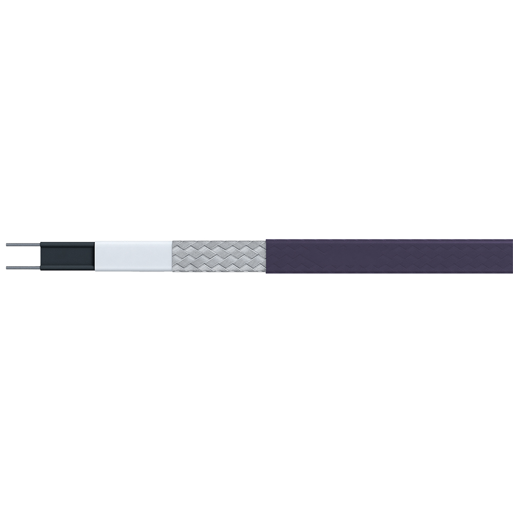
Self-Regulating Heat Trace Cable
Self-regulating (SR) cable is the most widely used type for commercial and residential freeze protection. Its heating element is a conductive polymer matrix—a carbon-loaded plastic core—sandwiched between two parallel bus wires. As temperature increases, the polymer core expands microscopically, reducing the number of conductive carbon particle contact points and increasing electrical resistance. Higher resistance means lower current flow and reduced heat output. As the cable cools, the polymer contracts, resistance drops, and heat output increases automatically.
This self-regulation happens at every point along the cable independently, meaning a section of cable near a warm pipe fitting automatically produces less heat than a section near a cold air pocket—without any thermostat or controller. This makes SR cable highly energy-efficient and eliminates the risk of overheating at overlaps or tight bends. SR cable can be cut to any length in the field, which simplifies installation significantly compared to constant wattage types.
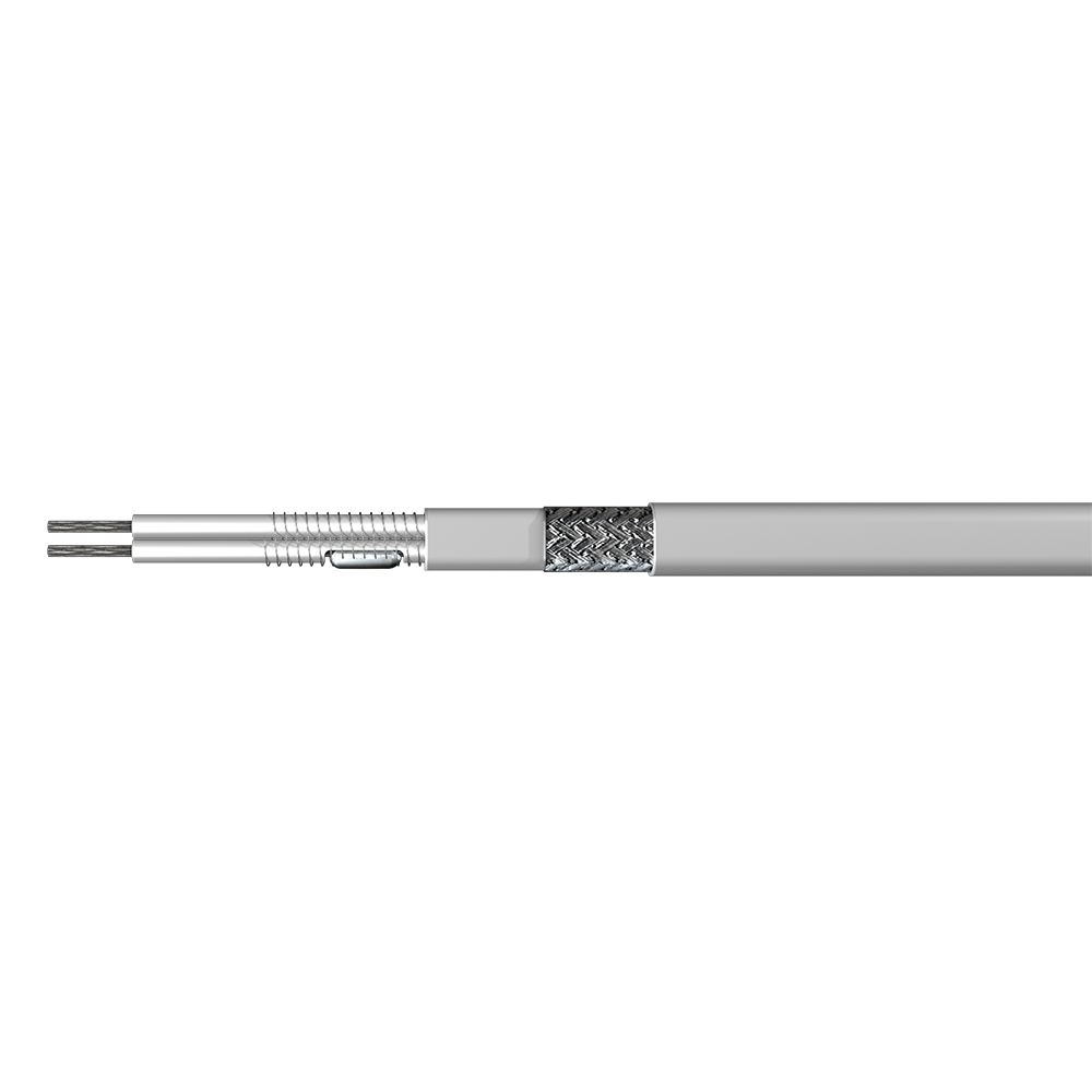
Constant Wattage Heat Trace Cable
Constant wattage (also called zone heating or ZTC) cables output a fixed wattage per foot regardless of ambient temperature. The resistive heating wire is wound around a fiberglass core at calculated intervals, creating discrete heating zones. Because wattage does not self-regulate, constant wattage cables require an external thermostat to prevent overheating—they cannot be overlapped or coiled during installation. They are preferred for very long pipe runs (up to several thousand feet from a single circuit) where the fixed resistance of SR cable would cause voltage drop and uneven heating.
Mineral Insulated (MI) Cable
MI cables use a metallic alloy resistance wire enclosed in a compressed magnesium oxide insulator inside a metal sheath. They handle temperatures up to 593°C and are mechanically robust enough for hazardous area classifications and steam-line tracing where polymer-based cables would fail. MI cable is the most expensive heat trace option per foot but is irreplaceable in high-temperature industrial applications—refineries, chemical plants, and power generation facilities where other cable types cannot survive the environment.
Common Applications of Electrical Tracing
Heat tracing serves a broader range of industries and use cases than most people realize. The unifying requirement in every case is maintaining a minimum or target temperature in a system where natural heat or ambient conditions are insufficient.
Residential and Commercial Freeze Protection
- Water supply pipes in exterior walls, crawl spaces, and unheated garages—the most common residential application. A burst pipe from freezing causes an average of $11,000 in damage according to U.S. insurance industry data, making a $50–$150 heat trace installation a straightforward investment.
- Roof and gutter de-icing using self-regulating cable in a zigzag pattern along roof edges and inside gutters, preventing ice dam formation that causes water infiltration and structural damage.
- Sprinkler system supply lines in fire protection systems where wet pipe runs pass through unheated spaces.
- Driveway and walkway snowmelt systems embedded in concrete or pavement, eliminating manual snow removal in high-traffic commercial areas.
Industrial Process Temperature Maintenance
- Oil and gas pipelines: Heavy crude, wax-bearing oil, and bitumen solidify when cooled below their pour point. Heat tracing maintains these fluids above their flow threshold across exposed above-ground pipe sections and instrumentation lines.
- Chemical processing: Many process chemicals (sulfur, caustic soda, acids, resins) solidify, crystallize, or become dangerously viscous at ambient temperatures. Electrical tracing keeps these materials flowable and prevents costly blockages and pipe ruptures.
- Instrumentation and analyzer lines: Sample tubing, impulse lines, and instrument taps connected to process equipment must remain above freezing (or above the process fluid's solidification point) to deliver accurate readings—a critical safety requirement in plant operations.
- Food and beverage processing: Chocolate, edible oils, glucose syrups, and dairy products require maintained temperatures during transfer to prevent solidification and contamination.
Heat Trace System Components Beyond the Cable
A complete electrical tracing system consists of more than just the heating cable. Each component plays a specific role in system performance, energy efficiency, and safety.
- Thermostat or temperature controller: Monitors ambient or pipe temperature and switches the heat trace circuit on and off to maintain the setpoint. Electronic controllers with ambient-sensing thermostats reduce energy consumption by up to 50% compared to systems running continuously. More advanced proportional controllers maintain tighter temperature control for critical process applications.
- Power connection kit: The termination assembly where the cable connects to the electrical supply. Includes a waterproof end seal, bus wire terminations, and a ground braid connection. Proper installation of the power connection is critical—improper termination is the leading cause of heat trace circuit failure.
- End seal kit: Seals the non-powered end of the heat trace cable against moisture ingress. A missing or damaged end seal allows water to wick into the cable core, causing insulation resistance failure and circuit faults.
- Splice kit: Used to join two sections of heat trace cable where continuous runs are not possible. Maintains waterproof integrity and electrical continuity at the junction point.
- Thermal insulation: Applied over both the pipe and the heat trace cable to minimize heat loss to the environment. Insulation type and thickness are engineering decisions that directly affect how much cable wattage is required—a well-insulated system may need 40–60% less cable wattage than an uninsulated equivalent.
- Monitoring and alarm panel: In industrial applications, heat trace monitoring systems perform continuous ground fault detection, current measurement, and alarm annunciation—critical for large plants with hundreds of heat trace circuits where manual inspection is impractical.
How to Size and Select a Heat Trace System
Selecting the correct heat trace cable wattage requires a simple heat loss calculation. The cable must output at least as much heat as the pipe loses to the environment under the worst-case ambient conditions at the installation site.
Basic Heat Loss Calculation Approach
Heat loss from an insulated pipe is calculated as: Q = (Tpipe − Tambient) ÷ Rthermal, where Q is heat loss in watts per foot, T values are in degrees Fahrenheit or Celsius, and Rthermal is the thermal resistance of the insulation system. Most heat trace manufacturers publish heat loss tables and online calculators that perform this calculation given pipe diameter, insulation type, insulation thickness, and design ambient temperature—eliminating the need for manual calculation in most field applications.
As a practical example: a 2-inch steel water pipe maintaining 40°F (4°C) in a −20°F (−29°C) ambient environment with 1-inch fiberglass insulation requires approximately 8–10 watts per foot of cable output. A 3 W/ft residential SR cable would be insufficient; a 10 W/ft SR cable or higher-output constant wattage cable would be appropriate.
Key Design Inputs
- Minimum ambient temperature: The lowest expected temperature at the installation site—use historical winter extremes, not averages, for freeze protection design.
- Maintain temperature: The minimum acceptable temperature inside the pipe or vessel—typically 40°F (4°C) for freeze protection, or the process fluid's minimum flow temperature for process maintenance.
- Pipe material and diameter: Larger diameter pipes have more surface area and greater heat loss; metal pipes conduct heat more efficiently from cable to fluid than plastic pipes.
- Insulation type and thickness: The single largest variable in system wattage requirements after ambient temperature—always insulate as well as physically practical before specifying cable wattage.
- Supply voltage: Heat trace cables are rated for specific voltage ranges (typically 120V or 208–277V). Using the wrong voltage results in significantly different watt output than designed—too low reduces heating capacity; too high can damage the cable or create a fire hazard.
Installation Basics and Common Mistakes to Avoid
Correct installation determines whether a heat trace system performs as designed for its full service life—often 10–20 years for quality SR cable in a well-maintained system. These are the practices that make the greatest difference.
- Apply the cable in direct contact with the pipe. Any air gap between the cable jacket and the pipe surface dramatically reduces heat transfer efficiency. Secure with aluminum foil tape every 12 inches—not plastic electrical tape, which insulates the cable from the pipe surface.
- Add extra cable at fittings, valves, and flanges. These components act as heat sinks—they absorb significantly more heat than straight pipe due to their mass. Wrap additional cable loops at each fitting as specified in the manufacturer's installation guide (typically one extra foot of cable per valve body).
- Never cut self-regulating cable to an exact circuit length without confirming maximum circuit length. SR cable has a maximum circuit length limit (typically 150–500 feet depending on wattage and voltage) determined by in-rush current at startup. Exceeding this trips breakers and stresses the cable.
- Test insulation resistance before and after installation. A megohmmeter test at 500V or 1,000V DC confirms the cable is undamaged before energizing. A reading below 20 megohms indicates a moisture or damage issue requiring investigation before the system goes live.
- Protect the cable from mechanical damage during insulation installation. The most common field damage to heat trace cable is compression or pinching from insulation jacketing being improperly applied over the cable—train installation crews to handle the cable with the same care as electrical wiring.
 English
 русский
 Français
 Español
 عربى
عربى