Pipework trace heating is an essential frost protection and temperature maintenance solution used across residential, commercial, and industrial settings. By applying controlled heat directly along the length of a pipe, trace heating systems prevent freezing, maintain fluid viscosity, and ensure process temperatures remain stable regardless of ambient conditions. This guide covers how trace heating works, the main system types, installation considerations, and how to select the right solution for your specific application.
What Is Pipework Trace Heating?
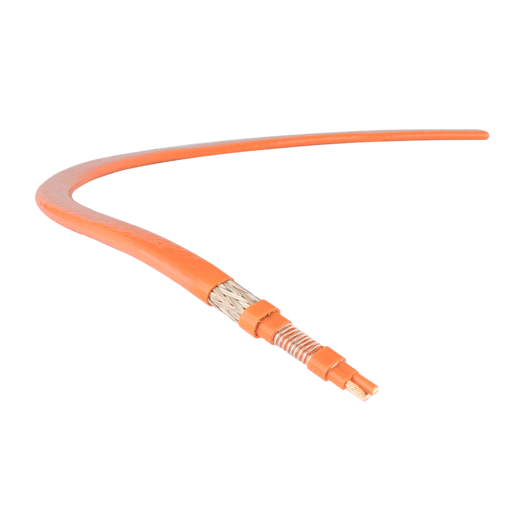
Trace heating — also referred to as heat tracing or surface heating — involves attaching an electric heating element or a steam/hot fluid tube along the exterior of a pipe to compensate for heat loss to the surrounding environment. The heating element runs parallel to the pipe, held in place with aluminium tape or fixings, and is then covered with pipe insulation to improve efficiency and retain heat.
The principle is straightforward: the trace heater replaces exactly the amount of heat the pipe loses to the surrounding air, keeping the pipe and its contents at or above the required minimum temperature. In frost protection applications, this minimum is typically 3°C to 5°C above freezing. In process temperature maintenance, targets can range from 20°C to over 200°C depending on the fluid being carried.
Where Pipework Trace Heating Is Used
Trace heating is applicable across a broad range of industries and settings. Common applications include:
- Frost protection: Domestic water supply pipes, outdoor pipework, and external fire sprinkler systems in cold climates.
- Industrial process heating: Maintaining viscosity in oil, chemical, and food-grade pipelines where the fluid must remain at a set temperature to flow correctly.
- Roof and gutter de-icing: Preventing ice dams and blocked drainage on commercial and industrial rooftops.
- Floor drainage and waste pipes: Keeping drain lines free-flowing in cold storage facilities and refrigerated warehouses.
- Offshore and petrochemical installations: Temperature maintenance for crude oil, gas condensate, and chemical transfer lines.
Types of Trace Heating Systems
There are two primary categories of pipework trace heating: electric and steam/hot fluid. Within electric trace heating, systems are further divided by cable type.
Constant Wattage Electric Trace Heating
Constant wattage cables deliver a fixed power output per metre regardless of ambient temperature. They are simple, reliable, and well-suited to short pipe runs or applications where the required heat output is consistent. However, because they cannot self-regulate, they must be used with an external thermostat to avoid overheating when ambient temperatures rise. Typical outputs range from 10W/m to 33W/m.
Self-Regulating Electric Trace Heating
Self-regulating cables are the most widely used type in modern installations. Their conductive polymer core automatically increases power output as temperature drops and reduces output as the pipe warms — all without any external controls. This makes them energy-efficient, safe against overheating, and capable of being overlapped without risk of hot spots. They are the preferred choice for frost protection on water pipes and general commercial applications.
Mineral Insulated (MI) Trace Heating
Mineral insulated trace heating cables use a copper or alloy resistance element surrounded by compacted magnesium oxide insulation within a metal outer sheath. They can withstand sustained temperatures of up to 500°C or higher, making them the standard choice for high-temperature industrial and hazardous area applications where polymer-based cables would degrade. MI cables are robust, have an exceptionally long service life, and are suitable for use in explosive atmospheres when paired with appropriate terminations and control equipment.
Steam and Hot Fluid Tracing
In large-scale industrial facilities that already operate a steam distribution network, steam tracing remains cost-effective. A small-bore steam tube runs alongside the process pipe, transferring heat through contact and radiation. While installation costs can be lower where steam infrastructure exists, steam tracing offers less precise temperature control than electric systems and requires regular maintenance of steam traps and condensate return lines.
| System Type |
Max Temperature |
Self-Regulating |
Best Application |
| Constant Wattage |
Up to 65°C |
No |
Short runs, consistent load |
| Self-Regulating |
Up to 120°C |
Yes |
Frost protection, water pipes |
| Mineral Insulated |
500°C+ |
No |
High-temp industrial, ATEX zones |
| Steam Tracing |
Varies |
No |
Large industrial sites with existing steam |
Table 1: Comparison of trace heating system types and their key characteristics
Designing a Pipework Trace Heating System
A correctly designed trace heating system begins with a heat loss calculation. This determines how much power per metre is required to maintain the pipe at the target temperature given the lowest expected ambient temperature, the pipe diameter, and the insulation specification. Undersizing a system leads to freeze failures; oversizing wastes energy and increases running costs.
Key design inputs include:
- Minimum ambient temperature: The coldest recorded or design temperature the system must handle.
- Pipe maintenance temperature: The minimum acceptable temperature of the pipe contents.
- Pipe material and diameter: Metal pipes conduct and lose heat differently from plastic pipes.
- Insulation type and thickness: Better insulation dramatically reduces the wattage per metre required and lowers running costs.
- Exposure conditions: Pipes exposed to wind require higher heat outputs than those in sheltered or indoor locations.
For complex installations or long pipe runs, most trace heating manufacturers provide sizing software and technical support to assist with system design.
Installation Requirements and Best Practices
Trace heating installation must comply with relevant electrical standards — in the UK, this means BS EN 60079 for hazardous areas and BS 7671 (IET Wiring Regulations) for general electrical installations. In the EU, ATEX directive compliance is mandatory for explosive atmosphere zones.
The following installation practices are critical for system reliability and longevity:
- Apply aluminium adhesive tape over the cable: This improves thermal contact between the cable and the pipe surface and distributes heat more evenly around the pipe circumference.
- Install insulation immediately after the cable: Exposed trace heating operates at significantly reduced efficiency and may fail to maintain temperature in severe conditions.
- Use manufacturer-specified end terminations and junction boxes: Improper terminations are the leading cause of trace heating failures and can create fire or electric shock hazards.
- Spiral cables on valves, flanges, and fittings: These fittings represent significant heat loss points and require additional cable coverage, typically spiralled around the component.
- Test insulation resistance before energising: A megohm test (typically 1,000V DC) should be carried out after installation to verify cable integrity before the system is powered.
Control and Monitoring Options
Effective temperature control reduces energy consumption and extends the service life of trace heating cables. The main control approaches are:
Ambient Sensing Thermostats
These switch the trace heating on when outdoor air temperature drops below a set point — commonly 3°C — and off when it rises above it. They are low-cost and simple to install, making them the standard choice for domestic frost protection. The drawback is that they heat the pipe regardless of actual pipe temperature, which can result in unnecessary energy use during mild periods.
Pipe Sensing Thermostats
A temperature sensor attached directly to the pipe surface gives more precise control, activating heating only when the pipe itself approaches the minimum temperature threshold. This approach is more energy-efficient and is recommended for process temperature maintenance applications.
Electronic Trace Heating Controllers
For large or critical installations, dedicated electronic controllers provide multi-circuit monitoring, alarm outputs for cable failures or temperature deviations, energy logging, and remote communication via BMS or SCADA integration. These systems are standard in industrial process plants where unplanned downtime from a freeze event carries significant financial consequences.
Running Costs and Energy Efficiency
The running cost of a trace heating system depends on cable wattage, the number of hours the system operates annually, and the local cost of electricity. A well-insulated pipe with a self-regulating cable and thermostat control is significantly cheaper to run than an uninsulated pipe with a constant wattage cable operating continuously.
As a practical example: a 10-metre domestic frost protection circuit rated at 10W/m, controlled by an ambient thermostat operating for approximately 1,000 hours per year, consumes around 100 kWh annually — equivalent to roughly £25–£35 per year at typical UK electricity rates. Industrial installations with longer runs and higher wattage requirements will have proportionally higher costs, making insulation specification and controller selection significant factors in lifecycle cost analysis.
Maintenance and Inspection
Electric trace heating systems are generally low-maintenance, but periodic inspection is important — particularly for safety-critical applications such as fire sprinkler pipe protection or hazardous area installations. A recommended annual maintenance routine includes:
- Visual inspection of cable condition, end seals, and junction boxes for signs of physical damage, moisture ingress, or corrosion.
- Insulation resistance test to confirm cable integrity has not degraded.
- Thermostat calibration check to ensure the control set points remain accurate.
- Verification that all circuit breakers and RCDs protecting the trace heating circuits are operational.
- Review of insulation condition — damaged or compressed pipe insulation reduces system efficiency and increases running costs.
Keeping a maintenance log for each circuit, including test results and any remedial actions, is good practice and is a requirement under many industrial safety management systems.
 English
 русский
 Français
 Español
 عربى
عربى