Consider a 150 m carbon-steel fuel-oil line at a terminal: at -10°C ambient, the line may lose 2–4 kW depending on insulation and wind. Without heating trace, the oil cools, viscosity rises, and the transfer pump can starve long before the line reaches the tank. The useful conclusion is that heating trace is a thermal circuit, not a cable accessory. It must be sized from heat loss, maintain temperature, environment, control, and installation method. Miss any of those and a well-made cable still becomes a maintenance problem.
Heating trace, also called heat tracing or electric trace heating, applies controlled heat to a pipe, tank, instrument, or duct surface to replace heat lost to the surroundings. It can do two different jobs: freeze protection, where the goal is to keep water-based fluids above 0°C with a safety margin, and process temperature maintenance, where the goal is to hold a product at a viscosity, flow, or reaction condition. The two jobs look similar on a drawing but require different power density, cable type, sensors, and alarms.
What heating trace is and what it is not
It is not a substitute for insulation. Insulation reduces heat loss; trace heating makes up the remaining loss. If insulation is wet, damaged, or missing at flanges and valves, the trace circuit runs longer and hotter. That shortens cable life and can push a self-regulating cable outside its useful adjustment range. The practical rule is to fix the thermal envelope first, then size the trace cable for the real heat loss.
It is also not a single product. A complete circuit normally includes the heating cable, cold lead, glands, junction boxes, thermal insulation, a thermostat or RTD sensor, a contactor or solid-state controller, earth-leakage protection, and alarms. In hazardous areas, the certification must cover the cable, glands, enclosures, and control cabinet as an assembly. A cable with an ATEX or IECEx certificate is not enough if the junction box or control panel is ordinary-duty.
Cable types at a glance
Typical heating trace cable choices and where each one fits best.
| Cable type |
Best for |
Practical watch-outs |
| Self-regulating |
Freeze protection, lower-temperature process lines, varying ambient conditions, and circuits that may be cut to length on site. |
Check start-up current, maximum exposure temperature, and the effect of repeated overlaps or tight bends on the manufacturer's output curve. |
| Constant wattage |
Higher maintain temperatures, longer three-phase runs, and duties where a stable output per metre is preferred. |
Cannot be overlapped unless the design allows it; circuit length and voltage drop must be checked carefully. |
| Mineral insulated |
High-temperature, high-power, or demanding industrial lines where mechanical and thermal robustness matter. |
Higher installation skill, limited field repair, and careful bending radius and end-sealing control. |
For three-phase constant wattage circuits on longer or higher-temperature runs, the cable and circuit design should be checked together, not selected from a catalogue temperature alone.
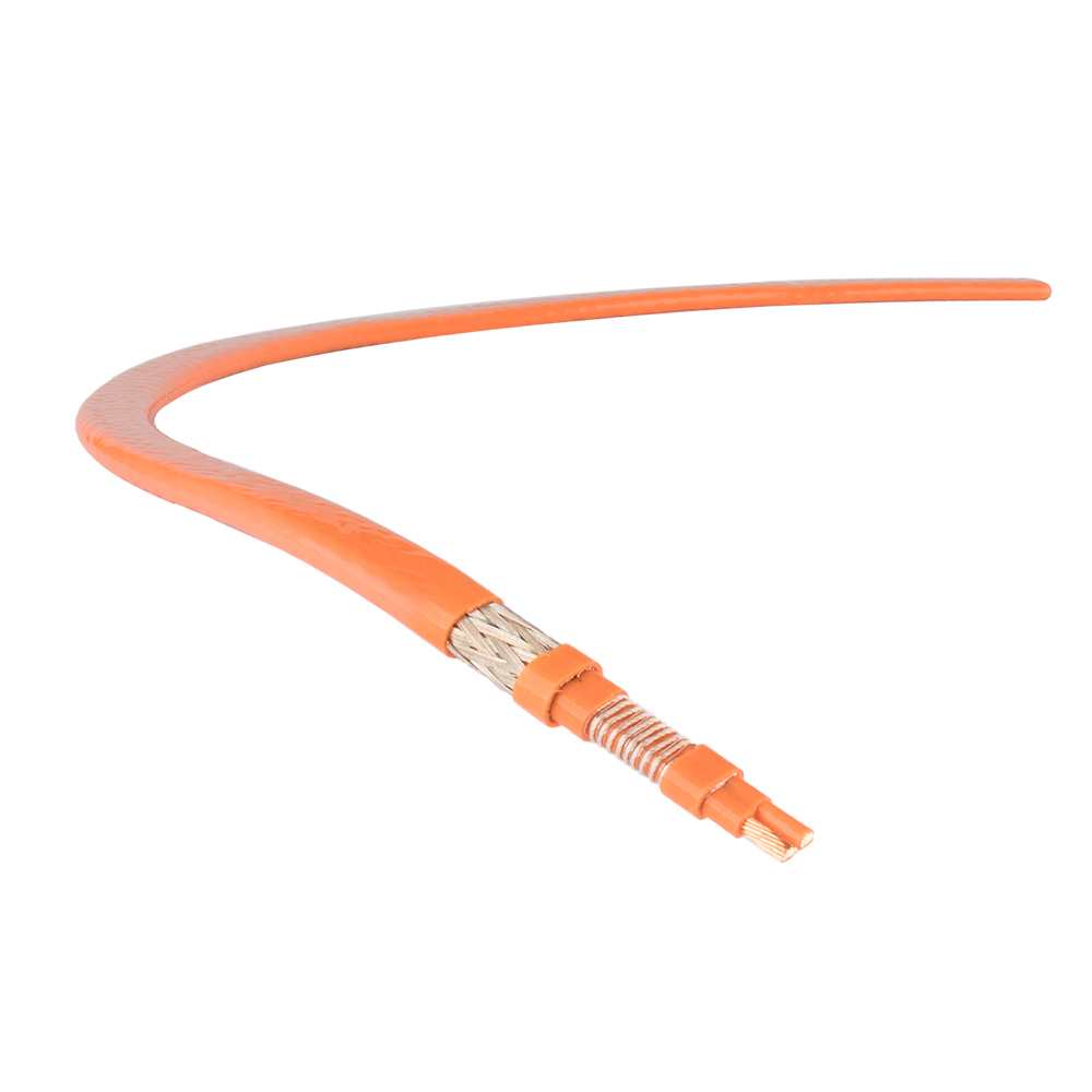 Constant Wattage Three-Phase Trace HeaterFor longer or higher-temperature three-phase runs, this heater keeps output constant per metre, can be cut on site, and suits viscous or corrosive process heating.View Product →
Start with heat loss and maintain temperature
Before choosing a cable, calculate or obtain the heat loss per metre at the lowest expected ambient and the required maintain temperature. A quote that lists only cable type and watts per metre is incomplete. The following data usually decides whether the circuit will work:
- Duty: freeze protection, viscosity control, or process temperature maintenance.
- Pipe or tank details: diameter, length, material, insulation thickness, and thermal conductivity.
- Temperature difference: minimum ambient, maintain temperature, and maximum exposure if the line is purged or cleaned.
- Power density and voltage: watts per metre, supply voltage, circuit length, and start-up current.
- Control philosophy: thermostat, RTD, proportional control, alarm, remote monitoring, and trip settings.
- Area classification and installation constraints: hazardous area, corrosion, washdown, offshore, or buried line.
If the supplier cannot show the calculation assumptions, the quotation is only a cable price. That matters because a trace circuit often fails at the weak point between cable, gland, junction box, and thermostat, not at the heating element itself. For a broader view of the cable, controls, and accessories in one place, see our heat trace product range.
Freeze protection: where the savings hide
Freeze protection is usually the most cost-sensitive application. The target is not to make the pipe hot; it is to keep the fluid above freezing with a reliable margin. A common design error is to ignore valves, flanges, dead legs, and instrument tappings. These fittings add surface area and thermal mass, so the cable layout and power allowance must cover them. A thermostat set at 5°C may be adequate for a well-insulated water line, but the sensor location matters: a sensor on the warm cable rather than on the pipe will cycle the circuit incorrectly.
Self-regulating cable is popular here because its output changes with temperature, but the circuit still needs earth-leakage protection, a contactor rated for the start-up current, and an alarm for loss of supply or low pipe temperature. Low-temperature maintenance trace heaters are often used for water lines, fire-protection piping, and small tanks where the maintain temperature is modest and the ambient swing is moderate.
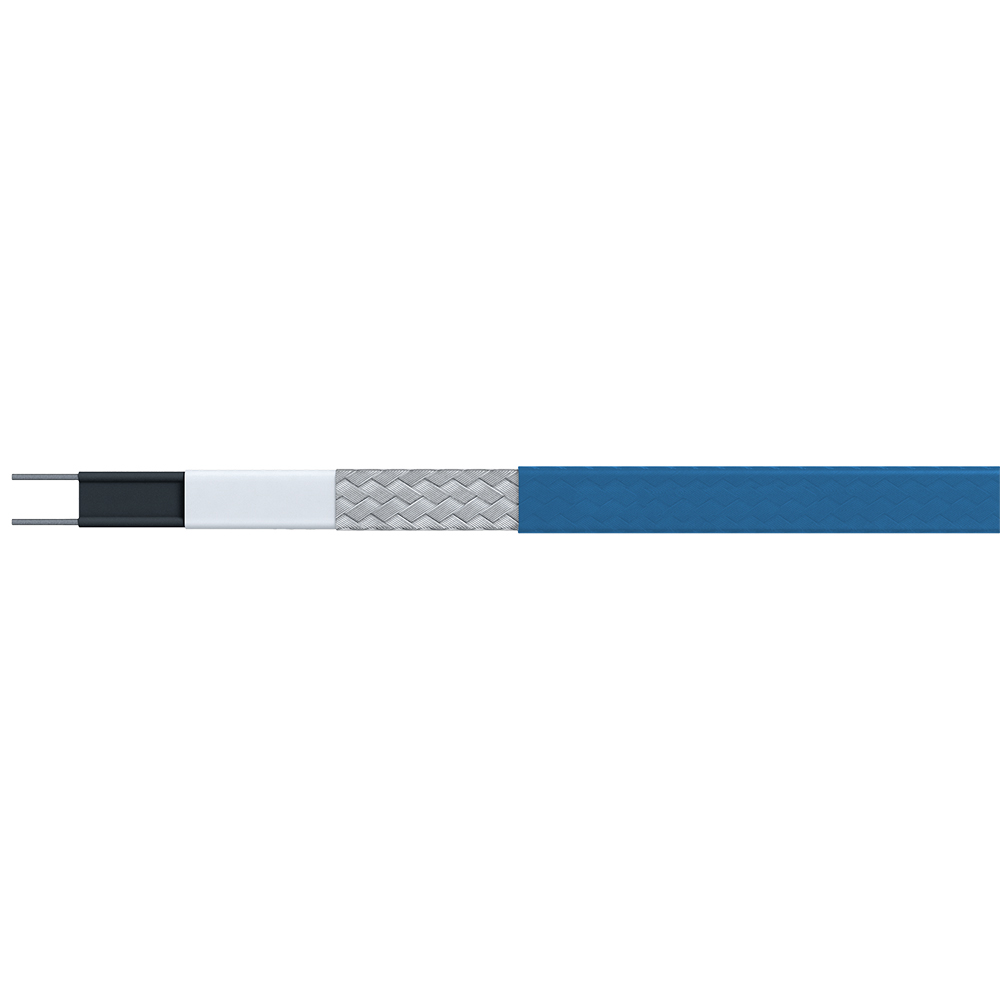 Low-Temperature Temperature Maintenance Trace HeaterWhere moderate maintain temperatures and frost protection are sufficient, this constant-wattage heater supports pipes, tanks, valves, and equipment in HVAC, water treatment, and food processing.View Product →
Process temperature maintenance: viscosity, flow, and product quality
Process lines are less forgiving. Heavy oil, bitumen, chemical transfer lines, and gas sample lines may need a maintain temperature well above ambient, and the permissible variation may be only a few degrees. In these duties, the cable type, sensor position, and control mode must be selected together. A constant wattage or mineral insulated cable may be better where the maintain temperature is high or where the line has repeated flanges and valves. Self-regulating cable is convenient for lower temperatures and varying ambient, but its maximum exposure temperature and start-up current still need checking.
Do not size by "maximum temperature" alone. The relevant figure is the maintain temperature under the worst heat-loss condition, plus a margin that the control system can manage. Oversizing a cable to cover uncertainty can overheat stagnant product, while undersizing it leaves the line below the required viscosity at the coldest hour of the night.
Control and hazardous area details that decide reliability
The control cabinet is not a box of contactors. It should define how the circuit starts, how it alarms, and how it fails. For freeze protection, a simple thermostat may be enough, provided the sensor is on the pipe and the alarm is visible. For process maintenance, an RTD and proportional controller usually give better results, especially where the line is partly idle. Earth-leakage protection is essential, but nuisance tripping is common when cable insulation is damaged during installation or when moisture enters an incorrectly sealed gland.
In a hazardous area, check the complete assembly: cable, glands, junction boxes, control cabinet, and temperature sensor. The area classification, gas group, and temperature class must be confirmed before the quotation is finalized. A hazardous-location trace control cabinet should include the required certification, correct enclosure protection, and a clear terminal layout for field testing.
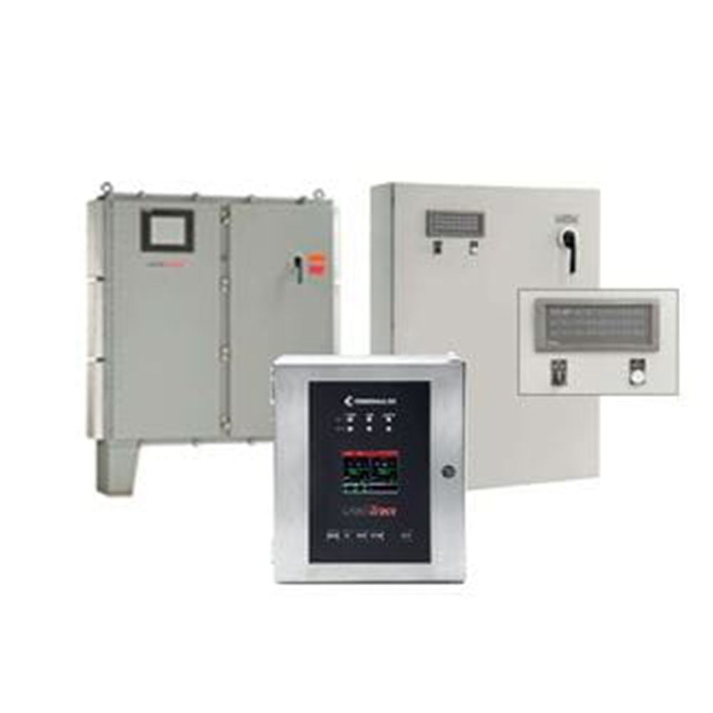 Heating Trace Control Cabinet for Hazardous LocationsFor hazardous-area trace heating assemblies, this cabinet combines temperature control, monitoring, and power management across 1 to 72 circuits for freeze protection and process maintenance.View Product →
Installation and commissioning: failures you can prevent
Most trace heating problems appear at commissioning or after the first cold snap. The cable may be electrically sound but thermally ineffective because it is not tight against the pipe, because insulation is wet, or because the sensor is in the wrong place. During installation, keep the cable off sharp edges, follow the specified bending radius, use the correct tape and thermal compound, and seal every gland. Do not energize the circuit until insulation resistance and continuity tests have passed.
- Record insulation resistance and loop resistance before and after insulation work.
- Label each circuit at both ends and update the panel schedule.
- Check thermostat and RTD calibration against a reference thermometer.
- Confirm alarm and trip settings with a simulated sensor signal.
- Photograph the cable layout before the insulation is closed up.
Our notes on construction and inspection standards offer a field-level checklist for these steps.
What to put in a heating trace inquiry
A useful inquiry gives the supplier enough information to size the circuit, not just sell a cable. Include pipe size and length, material, insulation type and thickness, minimum ambient, maintain temperature, maximum exposure temperature, supply voltage, area classification, control requirements, and any installation limits such as offshore transport or restricted access. If the line has valves, flanges, supports, or instruments, say so. Those details change the cable length and power allowance.
The final decision should be based on the thermal duty and the failure mode you can tolerate. Freeze protection can often accept a simple thermostat and self-regulating cable. A high-temperature process line may need constant wattage or mineral insulated cable, a dedicated control cabinet, and stricter commissioning records. In both cases, heating trace works best when the cable, insulation, sensor, control, and installation are treated as one system.

 English
 русский
 Français
 Español
 عربى

