A frozen line rarely fails at a convenient time. More often, the problem appears after a weekend shutdown, when a flange, a valve body, or a section of damaged insulation drops below the process minimum. The immediate question is usually which heat tracing cable to buy, but the better question is what duty the cable must perform. Heat tracing cables are not interchangeable reels of resistance wire; they are part of a system that includes controls, terminations, insulation, and installation practice.
Start with the heat loss calculation, not the cable price. A cable that delivers the right wattage at the wrong temperature, or with the wrong control strategy, can run continuously, trip a breaker, or leave a cold spot at the very place where freezing causes the most damage. The practical answer is to match the cable family to the pipe, the environment, the operating cycle, and the maintenance plan.
Start With Heat Loss, Not Cable Price
For a freeze protection circuit, the design case is the coldest ambient condition combined with the lowest acceptable pipe temperature. For process maintenance, the design case is the maintain temperature under worst-case ambient, wind, and insulation condition. Those two cases are different, and they often lead to different cable selections.
Useful inputs include pipe diameter and material, insulation type and thickness, minimum ambient temperature, maintain temperature, maximum exposure temperature, voltage and phase, available breaker size, area classification, and whether the line is normally full or empty. Valves, flanges, supports, and pump casings need attention because they create local heat loss that a straight pipe calculation ignores. A design margin of around 10 to 20 percent is common, but margin does not replace checking the details.
If the selected cable delivers 20 W/m while the line needs 28 W/m at design conditions, the controller will call for heat continuously and still miss the setpoint. The result is not simply a higher electricity bill. It is a circuit that has no reserve for insulation aging, a cold snap, or a wet cladding section.
- Confirm the maintain temperature and the maximum temperature the pipe may see during cleaning, steaming, or process upset.
- Check the minimum installation temperature, because some cables are harder to install in cold weather.
- Record the required circuit length and the available supply voltage before comparing cable families.
- Decide whether the circuit needs freeze protection only, process temperature maintenance, or high-temperature duty.
Match the Cable Type to the Duty
The three common families behave differently, and their catalogue wattage figures are not directly comparable. A self-regulating cable reduces output as the pipe warms, while a constant wattage cable delivers a fixed output per metre and depends on the controller to prevent overheating. Mineral insulated or high-temperature cables serve a different part of the market, where temperature, robustness, or fire resistance drives the choice.
One common procurement mistake is comparing watts per metre at a convenient reference temperature. A self-regulating cable rated at 30 W/m at 10°C may deliver far less at 120°C. If the specification only quotes the cold output, the installed circuit may be undersized for the actual maintain temperature. Ask for the output curve, the maximum circuit length, the minimum bend radius, and the recommended termination kit.
Comparison of common heat tracing cable families and the checks that matter at specification stage.
| Cable family |
Typical duty |
Control behaviour |
Checks before order |
Limits to respect |
| Self-regulating |
Freeze protection, lower-temperature process lines, valves, and small-bore piping |
Output falls as the pipe temperature rises |
Start-up current, minimum installation temperature, maximum circuit length, jacket material |
Long runs and high maintain temperatures need careful verification |
| Constant wattage |
Fixed process loads, grouped lines, and three-phase circuits |
Fixed output per metre; requires thermostat or controller |
Watt density, circuit resistance, zone control, termination method |
Overlap, incorrect zoning, or a failed controller can cause overheating |
| High-temperature or mineral insulated |
High-temperature process lines, harsh environments, and demanding installations |
Stable output at high temperature with robust construction |
Bend radius, terminations, moisture sealing, certified installation practice |
Higher installed cost and greater need for skilled workmanship |
For low-temperature maintenance and freeze protection, a temperature maintenance low-temperature trace heater is a practical starting point when the pipe stays within its operating envelope and the control strategy is simple. For fixed process loads where three-phase power is available, a constant wattage three-phase trace heater makes circuit design more predictable, provided the zones and thermostats are correctly arranged.
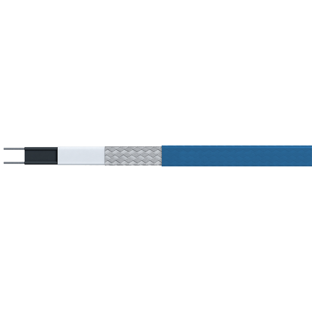 Temperature Maintenance Low-Temperature Trace HeaterA low-temperature heat trace option for pipe freeze protection and simple temperature maintenance, worth reviewing when moderate heat and straightforward control suit the project.View Product →
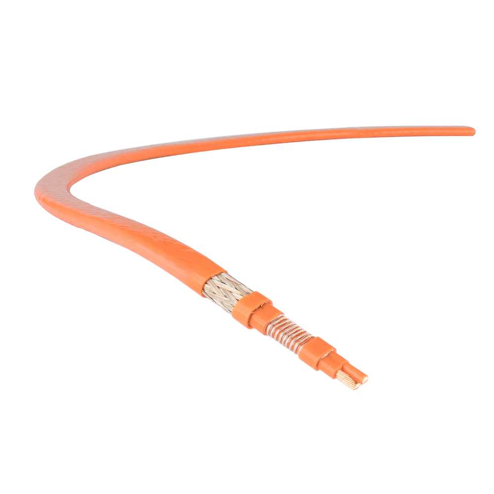 Constant Wattage Three-Phase Trace HeaterA three-phase constant wattage heater for fixed process loads and viscous materials, suitable when predictable circuit design and longer heated lengths are needed.View Product →
If you are comparing families for a project, review the heat trace product range before fixing the specification. The cable alone is only one line item; the termination kits, control panel, sensors, and installation labour usually determine whether the system is easy to maintain.
Hazardous Areas: Certification Is a System Property
In a hazardous area, the cable is not automatically safe because it carries a certification mark. The cable, joints, terminations, control cabinet, sensors, and installation method must suit the zone, gas group, and temperature class. A certified junction box fitted with an uncertified gland is still a weak point. The temperature class must also consider fault conditions, not only the normal setpoint.
Ask for the certificate scope and check that it covers the exact cable construction and accessory set being supplied. Confirm the ingress protection of enclosures, the maximum surface temperature, and the ambient rating of the control equipment. If the line is in a Zone 1 or Zone 2 area, the control cabinet and field terminations deserve as much attention as the heater cable itself.
A control cabinet for a hazardous location is part of the trace system, not an accessory. It should provide the required switching, protection, temperature sensing, and alarm contacts without compromising the area certification. For projects with limited maintenance access, remote alarm contacts and clear circuit labelling are worth specifying at the outset.
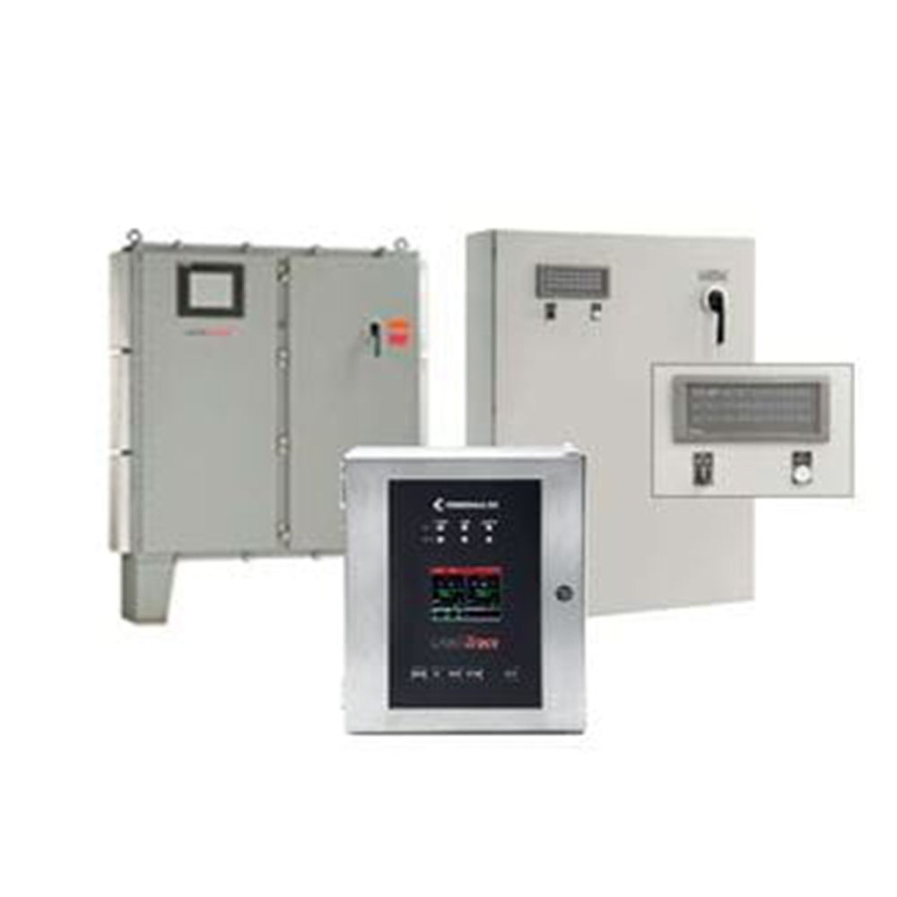 Heating Trace Control Cabinet for Hazardous LocationsA control cabinet for heat tracing that combines temperature control, protection, and monitoring across multiple circuits in hazardous and general environments.View Product →
Installation and Commissioning Checks That Prevent Callbacks
Most trace heating problems are visible before the system is energised. Cables laid over sharp edges, insulation pushed into a junction box, or a cold lead bent too tightly can create a fault that appears only after the first heating cycle. The installation should follow the approved drawing, the cable manufacturer's instructions, and the site's permit and inspection rules.
- Check that the cable, thermostat, junction boxes, and glands match the approved submittal and area certification.
- Inspect the pipe surface and insulation for sharp edges, moisture, and gaps that would create local cold spots.
- Install the cable without overlap, allow for expansion at flanges and valves, and protect it during cladding work.
- Measure insulation resistance and continuity before and after installation, then record the readings against the circuit number.
- After energising, verify the setpoint, alarm operation, and current draw, and update the as-built drawing with the final cable route.
For a more detailed field view, the construction techniques and inspection standards for electric heat tracing article is a useful reference for supervisors and QA teams. The main point is simple: a trace circuit that is not tested before insulation and cladding go on is much harder and more expensive to correct later.
Put These Details on the Inquiry Sheet
An incomplete inquiry often produces one of two results: a safe but expensive proposal, or a low price that fails at commissioning. Give the supplier enough information to select the cable and controls together. The following details remove most of the guesswork:
- Pipe size, material, length, and a simple sketch showing valves, flanges, pumps, and supports.
- Insulation type and thickness, minimum ambient temperature, maintain temperature, and maximum exposure temperature.
- Supply voltage, phase, frequency, available breaker size, and control voltage.
- Area classification, gas group, temperature class, and required ingress protection.
- Process medium, corrosion exposure, washdown, operating cycle, and whether the line may be empty or drained.
- Required control method, alarm contacts, circuit zoning, and the location of junction boxes and the control panel.
- Documentation needs: datasheets, certificates, test reports, installation instructions, and as-built drawings.
- Spare termination kits, installation support, and warranty terms.
This information also makes it easier to compare offers. A quotation that includes the correct control cabinet, certified terminations, and commissioning support may look higher at first, but it is usually cheaper than replacing an undersized cable or an incompatible gland after the line is insulated.
Lifecycle Cost and Maintenance
Heat tracing cables are long-life components only when the whole system is maintained. Insulation damage, a failed thermostat, or a loose termination can cause the controller to overheat the line or leave it unprotected. For critical freeze protection, use line sensing where the pipe temperature matters more than the ambient air, and fit alarms that are visible to the operations team rather than hidden inside a panel.
Keep the original design data, cable output curves, test records, and control settings with the maintenance file. Check insulation resistance at planned shutdowns and investigate any downward trend before the circuit fails. When a damaged section is replaced, use the same cable family, voltage, and output, and renew the termination kit rather than reusing old seals and glands. A spare kit on site is cheaper than a delayed restart.
The most reliable specification is not the one with the highest wattage or the longest warranty. It is the one that matches the heat loss, the environment, the certification requirements, and the way the plant is actually maintained. That is where heat tracing cables move from a catalogue item to a dependable part of the process.

 English
 русский
 Français
 Español
 عربى

