In any facility where flammable gases, combustible vapors, or explosive dusts are present, standard electrical equipment is not just inadequate — it is a direct ignition hazard. A single arc, spark, or surface temperature exceeding a material's auto-ignition point is enough to trigger a catastrophic event. Explosion proof electrical equipment is engineered to eliminate that risk: it either contains any ignition internally, prevents ignition from occurring at all, or removes the explosive atmosphere from contact with the electrical components entirely. Understanding how this equipment works, how hazardous areas are classified, and what certifications actually mean is the foundation of any safe and compliant installation in the oil and gas, chemical, petrochemical, pharmaceutical, or mining industries.
What Is Explosion Proof Electrical Equipment?
Explosion proof electrical equipment — also referred to as Ex equipment or hazardous area equipment — refers to devices and systems specifically engineered to operate safely in environments where an explosive atmosphere may be present. An explosive atmosphere forms when flammable gases, vapors, mists, or combustible dusts mix with air in concentrations capable of ignition.
The risk comes from the ignition triangle: fuel (the flammable substance), oxygen (present in air), and an ignition source. Standard electrical equipment can provide that ignition source through arcing at switch contacts, sparks from motor brushes, or surface temperatures on heating elements. Explosion proof equipment neutralizes this risk through one of several engineering strategies — containing any internal ignition, limiting energy below ignition thresholds, or physically separating the electrical components from the hazardous atmosphere.
It is important to note that "explosion proof" as used in North American standards (particularly UL and CSA) refers specifically to the containment approach: an enclosure rugged enough to contain an internal explosion and cool escaping gases below their ignition temperature before they reach the surrounding atmosphere. The broader international term is Ex equipment, which encompasses multiple protection concepts beyond containment alone.
Hazardous Area Classification: Zones and Classes
Before selecting any explosion proof electrical equipment, the hazardous area must be formally classified. Two parallel classification systems are in use globally: the Zone system (used under ATEX and IECEx in Europe and internationally) and the Class/Division system (used under NEC and Canadian Electrical Code in North America). Many facilities operating across regions must satisfy both.
Comparison of ATEX/IECEx Zone system and North American Class/Division system for gases and vapors
| ATEX / IECEx (Zone) |
North American Equivalent |
Description |
| Zone 0 |
Class I, Division 1 (severe) |
Explosive gas atmosphere present continuously or for long periods |
| Zone 1 |
Class I, Division 1 |
Likely to occur occasionally during normal operations |
| Zone 2 |
Class I, Division 2 |
Not likely under normal operations but possible under abnormal conditions |
| Zone 20 |
Class II, Division 1 |
Combustible dust present continuously or for long periods |
| Zone 21 |
Class II, Division 1 |
Combustible dust likely to occur occasionally during normal operations |
| Zone 22 |
Class II, Division 2 |
Combustible dust not likely under normal operations |
Gas group classification further narrows the selection: gases are grouped by their minimum ignition energy and maximum experimental safe gap. Group IIC (hydrogen) is the most hazardous and requires the highest level of protection; Group IIA (propane) is the least demanding within the flammable gas category. Equipment rated for Group IIC is suitable for use in IIB and IIA environments, but the reverse does not apply.
Types of Explosion Protection
International standard IEC 60079 defines over a dozen recognized protection concepts. The four most commonly encountered in industrial electrical and heating equipment are described below.
Flameproof Enclosure — Ex d
The Ex d concept is the most widely applied protection method for process equipment, switchgear, and heater terminal boxes. The enclosure is constructed with sufficient wall thickness and machined joint surfaces to contain any internal ignition without rupturing, and to cool any escaping hot gases below the ignition temperature of the surrounding atmosphere. This is the protection method used in the terminal housings of most industrial explosion proof heaters. Enclosures are typically cast from heavy-wall aluminum alloy or ductile iron and are substantially heavier than standard terminal heads.
Increased Safety — Ex e
Rather than containing an explosion after the fact, the Ex e approach applies additional engineering measures to prevent sparks, arcs, or excessive temperatures from occurring in the first place. This is commonly applied to terminal boxes, junction boxes, motors, and lighting fixtures where no arcing components are present during normal operation. Ex e equipment is often combined with Ex d in the same unit — for example, an immersion heater with an Ex d terminal enclosure and Ex e winding insulation.
Intrinsic Safety — Ex ia / Ex ib / Ex ic
Intrinsic safety limits the electrical energy available in the circuit — under both normal and fault conditions — to a level below what is required to ignite the hazardous atmosphere. This concept is widely used for instrumentation, sensors, and control wiring rather than for power-consuming equipment such as heaters or motors. Ex ia is the highest level, suitable for Zone 0; Ex ib is appropriate for Zone 1; Ex ic for Zone 2.
Pressurization — Ex p
Ex p protection maintains a positive internal pressure of protective gas (typically clean air or inert gas) inside the enclosure, preventing flammable atmospheres from entering and coming into contact with electrical components. This approach is commonly used for large control panels, analyzers, and variable speed drives that would otherwise be difficult or impractical to build into an Ex d enclosure. A purge-and-pressurization control unit monitors internal pressure and de-energizes the equipment if pressure drops below the safe threshold.
Key Certification Standards
Certification confirms that equipment has been independently tested and verified to meet the requirements of the applicable protection standard. The certification body, the standard applied, and the geographic region of installation all determine which certifications are required.
Major explosion proof certification frameworks and their primary regions of applicability
| Certification / Standard |
Region |
Basis |
| ATEX (Directive 2014/34/EU) |
European Union |
IEC 60079 series; mandatory for EU market |
| IECEx |
International |
IEC 60079 series; accepted in 50+ countries |
| UL 1203 / UL 60079 |
United States |
NEC Class/Division system; recognized by OSHA |
| CSA C22.2 No. 30 |
Canada |
Class/Division system; mandatory for Canadian installations |
| NEPSI / GB 3836 |
China |
Based on IEC 60079; required for Chinese domestic market |
For export-oriented manufacturers and global project contractors, IECEx certification is strategically valuable because it is mutually recognized by a growing number of national certification bodies, reducing the need for separate country-by-country testing. ATEX certification remains mandatory for equipment sold into the European Union regardless of IECEx status. Many reputable manufacturers — including those supplying industrial heaters to oil and gas projects — carry both ATEX and IECEx certifications on their explosion proof product lines.
Temperature Classification (T-Class)
Temperature classification is one of the most critical — and most frequently misapplied — parameters in explosion proof equipment selection. The T-class defines the maximum surface temperature that the equipment can reach under any operating condition, including fault conditions. This surface temperature must remain below the auto-ignition temperature (AIT) of every flammable substance that may be present in the installation environment.
IEC temperature classification: T-class designations and maximum allowable surface temperatures
| T-Class |
Max Surface Temperature |
Example Substance Requiring This Class |
| T1 |
450 °C |
Methane (537 °C AIT) |
| T2 |
300 °C |
Ethanol (365 °C AIT) |
| T3 |
200 °C |
Diesel fuel (210–220 °C AIT) |
| T4 |
135 °C |
Ethylene (125 °C AIT — requires T4 minimum) |
| T5 |
100 °C |
Carbon disulfide (90 °C AIT) |
| T6 |
85 °C |
Diethyl ether (160 °C AIT — use where lowest margin required) |
A higher T-class number imposes a more restrictive surface temperature limit, which typically requires lower watt density elements, more conservative thermal design, or active temperature control. A heater rated T3 is never suitable for an ethylene atmosphere, even if it carries a valid Ex d certification for all other parameters. Always obtain the AIT for every flammable substance potentially present before confirming T-class compatibility. For a full technical treatment of T-class selection in the context of liquid heating applications, refer to our explosion proof immersion heaters selection guide.
Explosion Proof Electric Heaters: A Practical Application
Among explosion proof electrical equipment categories, industrial electric heaters present a particularly demanding engineering challenge. A heater's core function — converting electrical energy into heat — means that high surface temperatures are intrinsic to the design. Managing those temperatures within T-class limits while maintaining heating efficiency requires precision in element watt density, sheath material selection, and thermal control architecture.
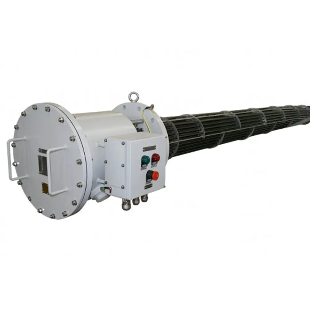
Explosion proof immersion heaters address this through two complementary approaches. The terminal housing — where wiring connects to the heating elements and where arcing could theoretically occur — is constructed as an Ex d flameproof enclosure, typically cast from heavy-wall aluminum alloy or ductile iron with machined flanged joints. The heating elements themselves are engineered for controlled, uniform watt density, with sheath materials selected for compatibility with the process fluid and operating temperature.
Common sheath materials for explosion proof immersion heaters include Incoloy 825 and 840 for general process fluids and oils, Inconel 600 and 625 for high-temperature and corrosive applications, Hastelloy C-276 for aggressive chemical environments, and titanium for seawater and chloride-bearing fluids. The combination of Ex d terminal enclosure and carefully specified element materials determines both the safety rating and the service life of the unit.
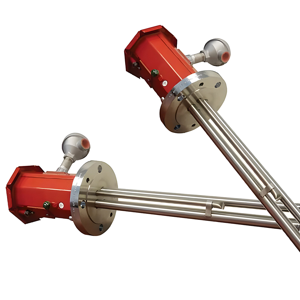
For facilities in Zone 1 and Zone 2 environments — including oil and gas processing, petrochemical plants, LNG terminals, and offshore platforms — two product configurations are commonly specified. The industrial explosion proof fluid immersion heater provides a versatile flanged design suitable for liquids, oils, and process gases across a wide power range, certified to ATEX and IECEx standards (Ex d, Ex e, IIC Gb, T1–T6) with IP66 ingress protection. For applications requiring easier in-field element replacement, the explosion proof flange immersion heater incorporates a hairpin element design with bite-coupling or direct-welding options that allow offline maintenance without removing the entire assembly from the vessel.
How to Specify Explosion Proof Electrical Equipment
Correct specification of explosion proof electrical equipment requires a structured approach that addresses each safety-critical parameter before any procurement decision is made. The following framework applies across equipment categories — from heaters and motors to junction boxes and instrumentation.
Step 1 — Establish the area classification
Obtain the formal hazardous area classification drawing for the installation site. Confirm whether the Zone system (ATEX/IECEx) or Class/Division system (NEC/CSA) applies. Identify the zone or division, the gas group, and the dust category if applicable.
Step 2 — Identify all flammable substances present
Compile the auto-ignition temperatures (AIT) of every flammable gas, vapor, or dust that may be present simultaneously or sequentially. The lowest AIT in the list determines the minimum required T-class. This step is frequently skipped or underestimated in facilities with multi-product processing or seasonal process changes.
Step 3 — Select the appropriate protection concept
Match the equipment type to the most suitable protection concept: Ex d for power equipment with arcing components; Ex e for terminal and junction boxes without arcing; Ex ia/ib for low-energy instrumentation and sensing circuits; Ex p for large panels or enclosures that cannot practically be built to Ex d dimensions.
Step 4 — Confirm certifications against project requirements
Verify that the equipment certificate (ATEX, IECEx, UL, CSA, or NEPSI) matches the jurisdiction of the installation and the specific zone, gas group, and T-class required. Check the certificate expiry date and confirm the certification body is accredited for the applicable standard.
Step 5 — Specify ingress protection (IP rating)
Outdoor installations, washdown environments, and dusty facilities require appropriate IP ratings independent of the explosion proof classification. IP66 provides protection against powerful water jets and heavy dust ingress and is the typical minimum for outdoor industrial installations. IP67 or IP68 may be required for submerged or frequently flooded locations.
Step 6 — Confirm material compatibility
For heaters, enclosures, and any wetted components, verify that the materials of construction are chemically compatible with the process fluid, the ambient environment, and the cleaning or sterilization procedures used at the facility. Corrosion-induced enclosure failure is a common cause of Ex equipment degradation in service.
 English
 русский
 Français
 Español
 عربى
عربى