A process plant in a northern climate loses a condensate return line at 4:30 AM. The temperature dropped to -18°C, the line froze, and the morning shift cannot start production. This scenario repeats every winter in facilities that underestimate the cost of an unheated pipe. A blocked line, including lost production, labor, and repairs, usually costs far more than a complete electrical heat tracing installation. That is why heat tracing is specified not as a convenience, but as a protective layer for process availability.
Electrical heat tracing is a controlled way of adding heat to pipes, tanks, valves, and instruments from the outside. It maintains fluid temperature or prevents freezing by compensating for heat lost through the thermal insulation. The rest of this article explains how it works, what cable types are available, how to select the right system, and what causes most field failures.
What Electrical Heat Tracing Does
An electrical heat tracing system consists of a heating cable laid along the pipe surface, thermal insulation installed over the cable, and a control system that switches power on and off. When current passes through the resistive element inside the cable, it generates heat. That heat transfers through the pipe wall into the fluid, balancing the heat lost through the insulation.
Heat tracing differs from immersion heating in one fundamental way: the heating element does not touch the process fluid. This makes it suitable for retrofitting existing lines, for long pipe runs, and for equipment where an internal heater would disturb flow or create a hot spot. Tracing also works on valves, flanges, supports, and instruments, areas where an immersion heater cannot be installed.
The Three Main Heat Tracing Cable Types
Selecting the right cable is the most important decision in any heat tracing project. The three dominant technologies are self-regulating, constant wattage parallel, and series constant power. Each has a distinct behavior, and the choice affects circuit length, control strategy, and installation practice.
Self-Regulating Cables
Self-regulating cables use a conductive polymer core between two bus wires. As temperature rises, the polymer resistance increases and heat output drops. This feedback effect means the cable naturally limits its own temperature. It can be cut to length in the field, and it can be overlapped without the risk of burnouts. It is the most common choice for freeze protection of small and medium pipes.
Constant Wattage Parallel Cables
Constant wattage cables have a heating wire wound around the bus wires and connected at intervals. The output per meter stays fixed regardless of pipe temperature. These cables provide higher and more consistent power than self-regulating types, but they must not be overlapped, and they require a thermostat to prevent overheating. They suit temperature maintenance where steady output is needed.
For applications that require stable output over medium distances, a flexible constant power heating cable with field-terminated cold leads and standardized connection kits is available.
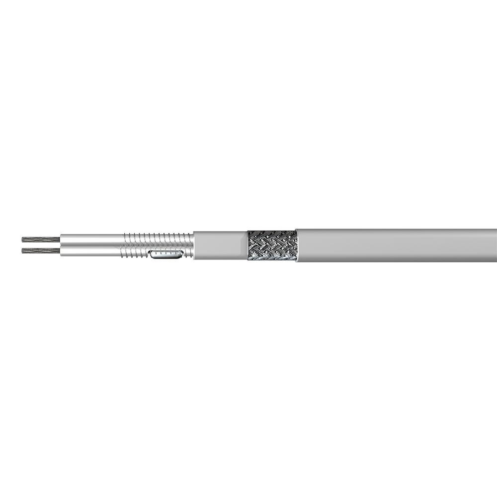 Flexible Constant Power Heating Cable for Process Heat TracingThis constant wattage cable maintains uniform heat output per unit length and can be cut to fit on-site, making it suitable for medium-length pipelines that require stable temperature control.View Product →
Series Constant Power Cables
Series cables use a single resistive conductor along the entire length. Power output is uniform along the circuit, and circuit lengths can extend for kilometers. This makes them ideal for long pipelines, loading lines, and applications where the electrical supply points are far apart. However, they must be designed and manufactured to a specific length, so planning is more critical than with parallel cables.
Comparison of the three main heat tracing cable types.
| Property |
Self-Regulating |
Constant Wattage Parallel |
Series Constant Power |
| Output behavior |
Decreases as temperature rises |
Fixed output per meter |
Uniform output along circuit |
| Field cutting |
Cut to length on site |
Cut to length at designated points |
Factory designed length |
| Overlap allowed |
Yes |
No |
No |
| Typical circuit length |
Up to 100 m |
Up to 200 m |
Kilometers possible |
| Best suited for |
Freeze protection of small pipes |
Temperature maintenance |
Long pipelines and high power |
Selection Criteria That Actually Matter
Start with the operating goal. Is the system preventing freezing, or maintaining a process temperature? Freeze protection allows a wider temperature band and simpler control. Temperature maintenance, especially for viscous fluids or exothermic processes, requires precise control and a cable power output that matches the heat loss at the lowest ambient temperature.
The heat loss calculation needs four inputs, and in practice you cannot skip any of them:
- Maintain temperature and the lowest expected ambient temperature
- Pipe size, wall thickness, and material
- Type and thickness of thermal insulation
- Expected wind exposure and installation environment
Once the heat loss per meter is known, you compare it with the cable output. A common safety margin is 10 to 20 percent, but oversizing beyond that wastes energy and can damage temperature-sensitive fluids. The fluid type also matters: heavy oil needs a higher maintain temperature than water, and a fluid that solidifies at ambient conditions requires a higher tracing power to recover after a shutdown.
Hazardous area classification changes everything. In explosive atmospheres, the cable, connections, and control cabinet must carry appropriate certification and be installed according to the zone requirements. A standard cable in a classified area is a direct safety violation.
For frost protection duty where the ambient temperature rarely drops below -20°C and the medium is water or a light process fluid, a high-temperature rated trace heater with moisture-resistant construction covers most outdoor installations.
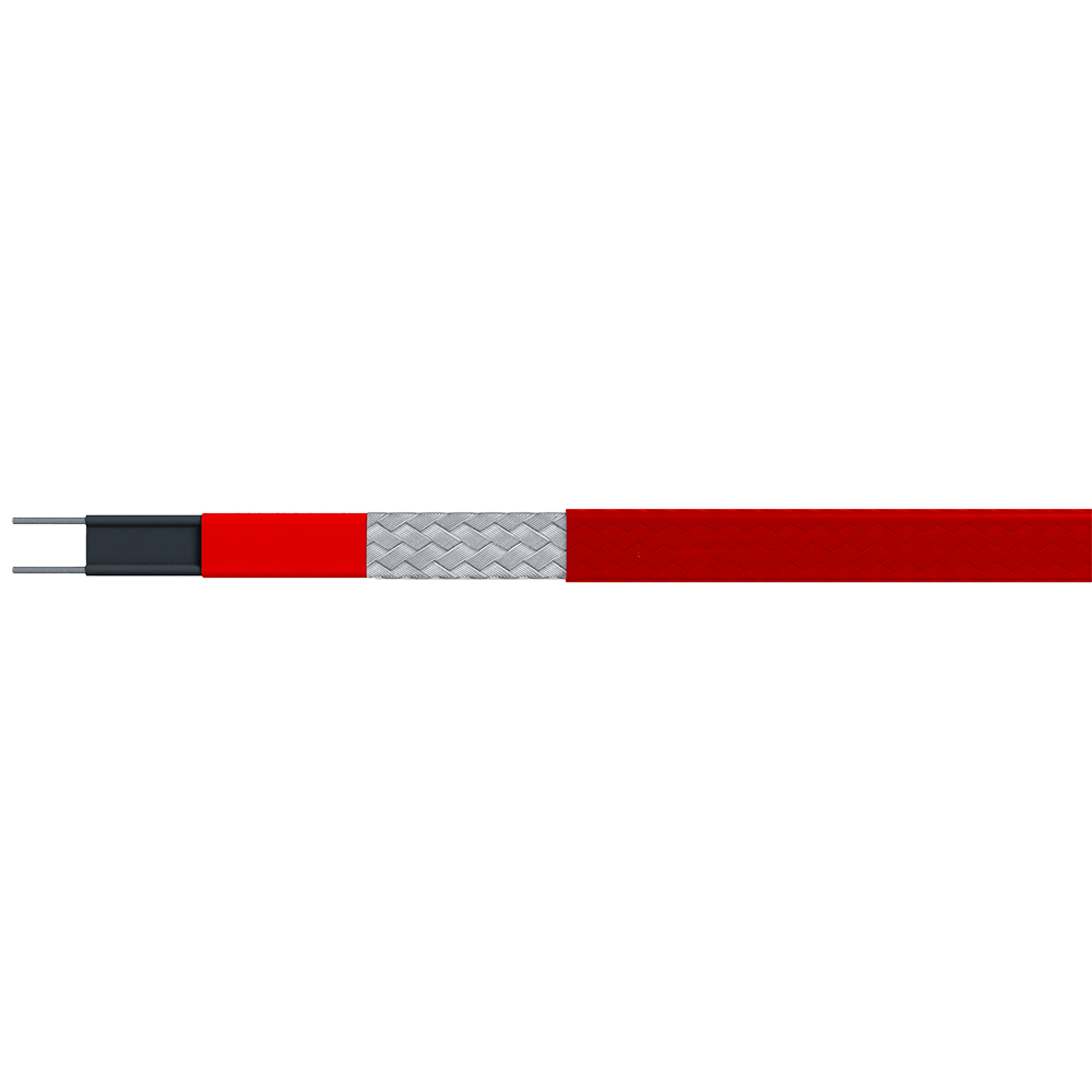 High-Temperature Trace Heater for Freeze ProtectionDesigned for frost protection in outdoor installations, this constant wattage heater operates reliably at high temperatures and suits pipes carrying water or light process fluids in moderate cold climates.View Product →
Installation Errors That Cause Most Failures
In the field, most heat tracing failures trace back to installation mistakes rather than cable defects. The cable must make full contact with the pipe surface; an air gap between the cable and the pipe acts as an insulation layer and creates a cold spot. Fixing the cable every 300 to 500 mm with approved tape or straps, not cable ties that can crush the jacket, is standard practice.
Sharp edges on pipe supports and flanges can cut the jacket during installation or during thermal expansion. The cable should be routed to avoid edges, or protected with a metal guard. Connections and terminations are the most vulnerable points. Every splice and end seal must be made with the manufacturer's approved kit and sealed against moisture. A single poorly sealed termination is the most common cause of ground-fault trips.
Before covering the cable with thermal insulation, measure the insulation resistance of each circuit. This test catches cable damage and moisture ingress early. The widely accepted minimum reading is 20 megohms, although new installations often read several hundred. Record the value for each circuit; it becomes the baseline for future maintenance.
Construction and inspection standards for electric heat tracing cover these points in detail, and they are worth reviewing before work starts on site.
Construction techniques and inspection standards for electric heat tracing.
Control Systems and Energy Efficiency
A heat tracing cable without a controller is a heater running at full capacity regardless of need. In a freeze protection application, that can mean energy wasted for months. A line-sensing thermostat placed on the pipe surface cuts power when the pipe temperature is above the set point, while an ambient-sensing controller responds to outside temperature. For temperature maintenance, a controller with a sensor placed on the pipe or directly on the fluid gives tighter control.
All heat tracing circuits should include ground-fault protection. The leakage current in a healthy heating cable is small, but a damaged jacket can create a path to ground that standard circuit breakers do not detect. A 30 mA ground-fault device protects both personnel and the system. In hazardous areas, the control cabinet must be approved for the zone and integrated with the rest of the protection philosophy.
Where the tracing runs through a classified area, the power and monitoring components belong in a certified enclosure designed for the location.
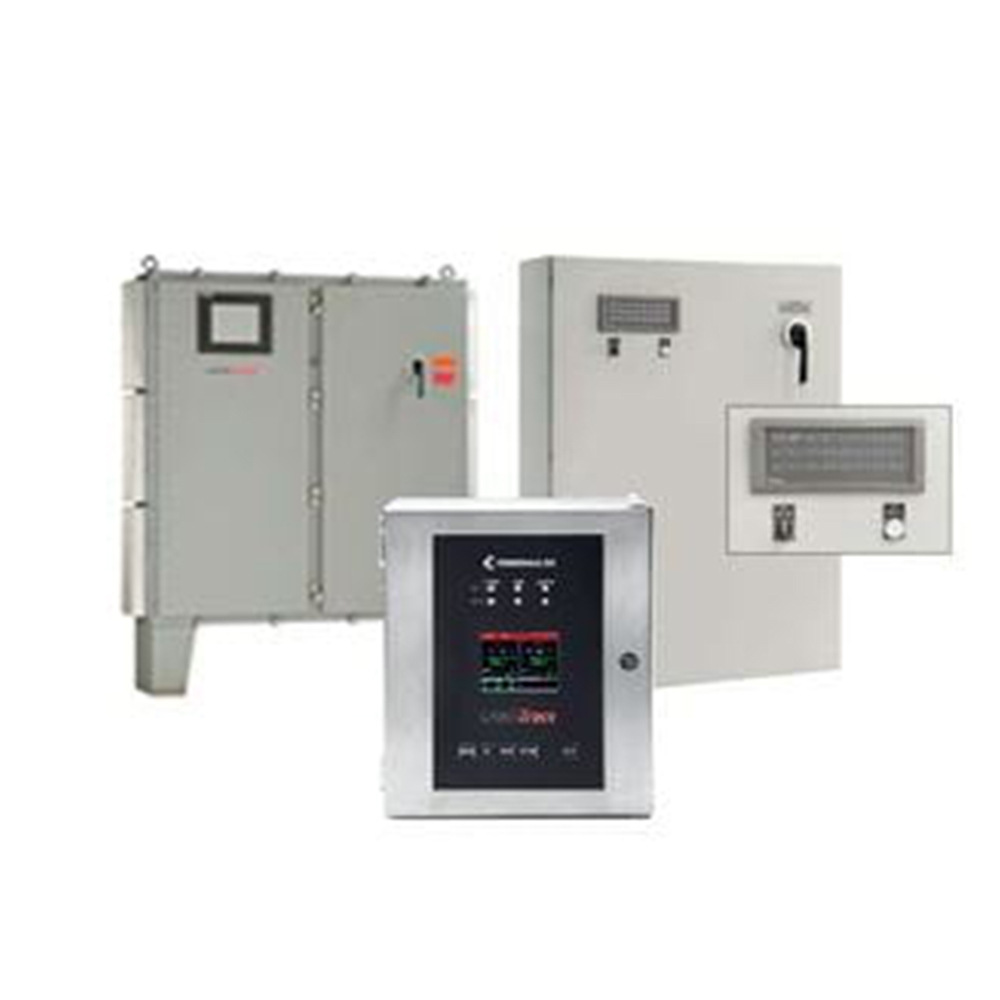 Heating Trace Control Cabinet for Hazardous LocationsThis certified control cabinet integrates temperature monitoring and power management for heat tracing circuits, providing safe operation in classified environments and supporting reliable maintenance checks.View Product →
Maintenance and Troubleshooting
The maintenance burden of a well-installed heat tracing system is low, but it is not zero. A yearly inspection before the cold season should include a visual check of the cable jacket for cuts, abrasion, or chemical attack; verification that insulation is intact and waterproofed; and an insulation resistance test compared with the installation baseline. A reading that drops by more than 25 percent from baseline signals a developing problem.
Common failure modes are moisture at terminations, mechanical damage from maintenance work on the pipe, and failed thermostats. When a circuit trips, check the controller first, then the termination, then the cable. Do not simply reset the breaker and walk away, because a ground fault that is not located will return.
Replacing a damaged section of self-regulating cable is straightforward when the manufacturer's splicing kit is used. For series constant power cables, the repair options are more limited, because the entire circuit may be affected.
The system design should already account for maintainability. Accessible connection boxes, labelled circuits, and a record of the design calculations make every future intervention faster and safer. A well-documented heat tracing system is an asset; an undocumented one is a liability waiting for a cold night.

 English
 русский
 Français
 Español
 عربى
عربى
