How Cable Gland Sizing Actually Works
An engineer ordered an M25 gland for a four-core 10 mm² cable, only to find that the cable's actual outer diameter was 16.2 mm. The gland's clamping range was 10–14 mm, so the seal could not close. That is the most common cable gland sizing mistake: choosing by conductor cross-section instead of cable outer diameter. Cable gland size is determined by cable outer diameter, cable construction, and the thread that connects the gland to the equipment.
A cable gland has two separate dimensions that matter:
- The thread size, which fits the hole on the enclosure, junction box, or motor frame.
- The cable clamping range, which is the minimum and maximum outer diameter of cable that the sealing insert can hold.
For armoured cables, the gland also has an armour clamping cone that grips the steel wire or braid. For unarmoured cables, only the outer sheath is sealed. Selecting a gland without checking both the thread and the cable outer diameter is the fastest way to create a leak point or lose the strain-relief function.
Metric Cable Gland Size Chart
Metric glands are common on European and Asian equipment. The "M" number refers to the nominal thread diameter in millimetres. For example, M20 means a 20 mm metric thread, usually with a 1.5 mm pitch. The cable diameter range is separate from the thread size and is listed in each manufacturer's datasheet.
Table 1. Typical metric cable gland sizes and accepted cable outer diameter ranges. Always verify with the supplier's exact datasheet.
| Thread Size |
Cable Outer Diameter Range |
Typical Use |
| M12 |
3.0–6.5 mm |
Sensors, instrumentation, thin control cables |
| M16 |
5.0–10.0 mm |
Control wiring, small power cables |
| M20 |
6.0–12.0 mm |
General power and control circuits |
| M25 |
10.0–14.0 mm |
Four-core power cables, medium feeders |
| M32 |
12.0–18.0 mm |
Larger multicore cables |
| M40 |
16.0–24.0 mm |
Heavy power feeders |
| M50 |
22.0–32.0 mm |
Supply cables to large equipment |
| M63 |
30.0–44.0 mm |
Main incoming supplies |
These ranges are typical values, not universal guarantees. Two cables with the same conductor size can have different outer diameters because of insulation thickness, armour, or overall sheath material. Always measure the actual cable before finalising the gland order.
PG Cable Gland Size Chart
PG stands for Panzerrohrgewinde, an older German thread standard that still appears in legacy panels and some European installations. PG sizes may look similar to metric sizes, but the thread dimensions are different and the two are not interchangeable.
Table 2. Typical PG cable gland sizes and accepted cable outer diameter ranges. Use as a guide, not a substitute for datasheet values.
| Thread Size |
Cable Outer Diameter Range |
Typical Use |
| PG7 |
3.0–6.5 mm |
Small sensors and signal cables |
| PG9 |
4.0–8.0 mm |
Control wiring |
| PG11 |
5.0–10.0 mm |
Light power and control cables |
| PG13.5 |
6.0–12.0 mm |
Standard control and power circuits |
| PG16 |
10.0–14.0 mm |
Four-core power cables |
| PG21 |
13.0–18.0 mm |
Larger multicore cables |
| PG29 |
18.0–25.0 mm |
Heavy power cables |
| PG36 |
22.0–32.0 mm |
Main supply feeders |
| PG42 |
30.0–38.0 mm |
Large industrial cables |
| PG48 |
34.0–44.0 mm |
Very large incoming cables |
The values in this chart are useful for planning, but the final choice must come from the gland manufacturer's dimensional table because the sealing range changes with the rubber compound and the design of the compression insert.
Metric vs PG: Why They Are Not Interchangeable
PG and metric threads have different thread profiles and pitches. Metric threads use a 60-degree ISO metric form, while PG uses the older 55-degree Whitworth form. The differences are small in appearance but substantial in fit. PG13.5 has a nominal outer diameter of 20.4 mm and a pitch of 1.41 mm; M20 has a 20 mm diameter and a 1.5 mm pitch. Forcing a PG gland into an M20 hole, or the opposite, can strip the thread, deform the sealing face, and destroy the ingress protection rating.
North American installations often use NPT threads, which are tapered pipe threads measured in inches. NPT is not compatible with metric or PG straight threads. If a project includes equipment from different regions, check the thread standard before ordering glands. Mixing thread standards is a common cause of on-site cable gland failure.
How to Measure a Cable Gland in Three Steps
You do not need to be a cable specialist to choose the right gland, but you do need three measurements and one clear look at the cable construction.
- Measure the cable outer diameter with a caliper. Take three readings around the cable at the same point and use the largest value. Cables are rarely perfectly round.
- Identify the thread on the equipment or junction box. Measure the thread diameter and pitch, or read the drawing. For metric threads, the pitch is often printed on the gland or enclosure.
- Confirm the cable type. Steel-wire-armoured cable requires a gland with an armour clamp. Unarmoured cable needs a plain sealing gland with an appropriate elastomer insert.
If your cable falls near the upper limit of a gland's range, choose the next larger size rather than relying on excessive compression. Over-compressing the seal shortens its life and can damage the cable sheath.
Common Cable Gland Sizing Mistakes
Most gland problems come from a small set of avoidable errors. Check these points before you place an order:
- Selecting by conductor cross-section instead of cable outer diameter.
- Ordering a metric gland for a PG threaded hole, or the reverse.
- Assuming that all cables with the same mm² rating have the same outer diameter.
- Ignoring the cable's outer diameter tolerance, which can be several tenths of a millimetre.
- Choosing a brass gland for a washdown or corrosive area without verifying the coating or material.
- Forgetting to check the thread length for thick-walled flameproof enclosures.
Why Correct Gland Sizing Matters in Heated Industrial Equipment
A wrong gland size is more than a paperwork problem. In a heating system, a poorly sealed cable entry can let moisture reach live terminals. In a hazardous area, the gland is part of the flameproof path, and a damaged or mismatched thread can break that path. That is why gland selection should be part of the overall system design, not an afterthought.
Immersion Heaters and Hazardous Areas
A high-power immersion heater draws enough current that a loose seal can quickly become a hot spot, especially if the heater is used in an area with washdown or condensation. For hazardous locations, every cable entry point must preserve the enclosure's protection concept. An ATEX-certified explosion-proof immersion heater takes some of the guesswork out of the terminal design, but the site cable still has to be matched to the correct gland. Once the gland is fitted, following the correct use and maintenance of explosion-proof electric heaters will help keep the whole assembly reliable.
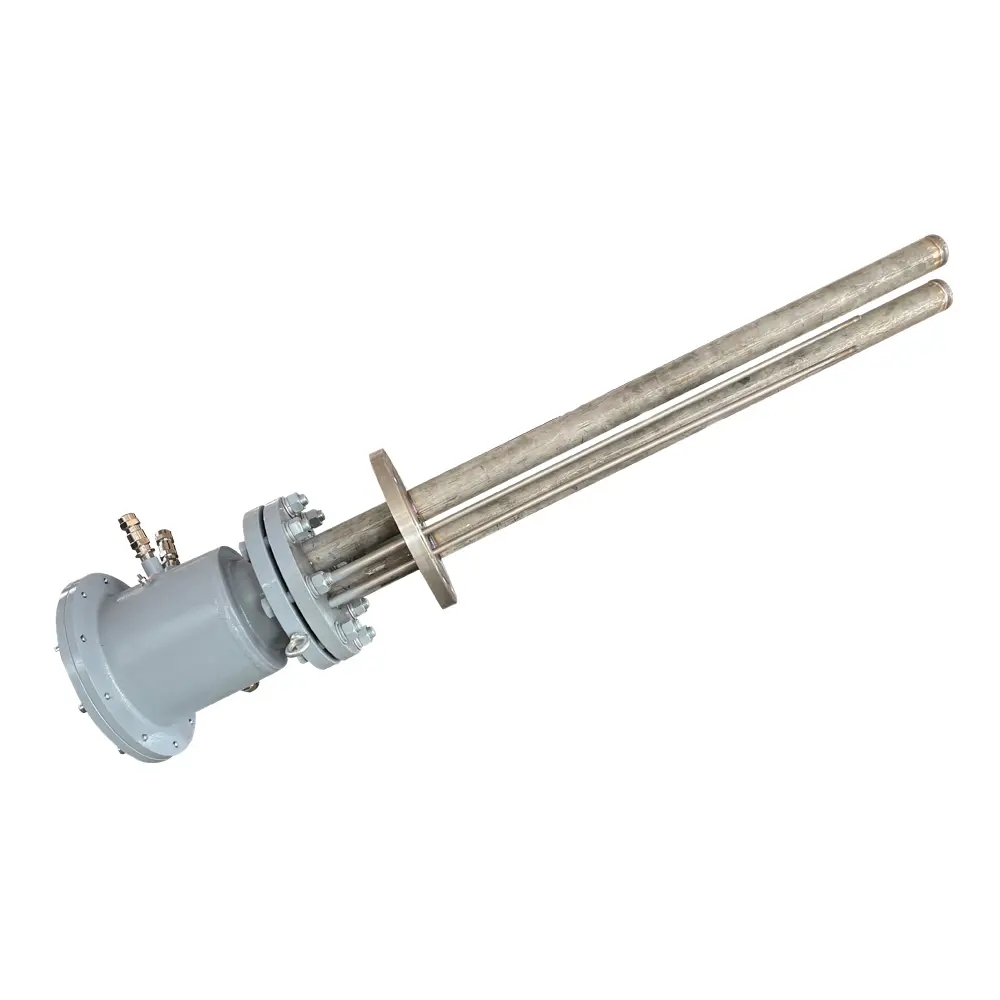 380V 6KW Industrial Explosion Proof Immersion Heater((ATEX Certified)) SuppliersWeineng Electric is China wholesale 380V 6KW Industrial Explosion Proof Immersion Heaters((ATEX Certified)) suppliers and 380V 6KW Indust...View Product →
Control Cabinets and Cable Entries
Heater control cabinets contain many cable entries, from the main power feed to temperature sensor wiring. If the panel drawing specifies M20 openings but the field cable needs M25, adapters reduce reliability. A flameproof control cabinet designed for all industrial branches is a practical choice when you need a certified enclosure with predictable thread sizes, but each gland must still be selected for the individual cable passing through it. The same step-by-step selection logic applies to other parts of the system, just as you would apply when you learn how to choose an air duct heater for a specific process condition.
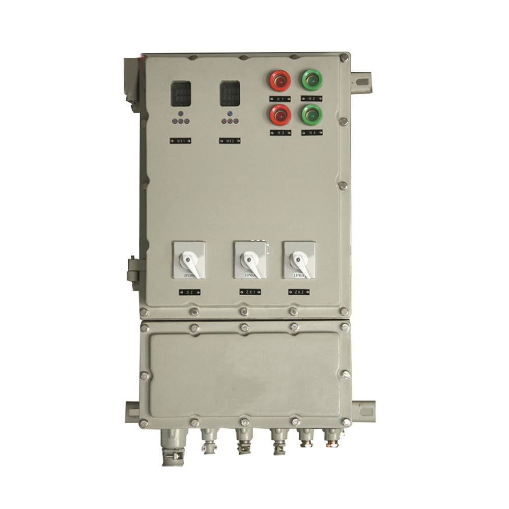 Flameproof Electric Control Cabinet Suppliers, CompanyJiangsu Weineng Electric is China Flameproof Electric Control Cabinet Suppliers and Company, we offer Custom Industrial Branches Flamepro...View Product →
Trace Heating and Low-Temperature Installations
Heat tracing systems often use small-diameter heating cables that are easily damaged by an oversized gland. The gland must hold the cold lead and the heating cable without crushing the insulation. Preassembled kits remove a large part of the risk because the supplier has already matched the fittings. Trace heater installation kits and accessories are designed for this type of work, so the installer does not have to combine parts from different sources. Before energising the circuit, check the electric heat tracing construction and inspection standards to confirm that every fitting, including the gland, meets the required mechanical and electrical levels.
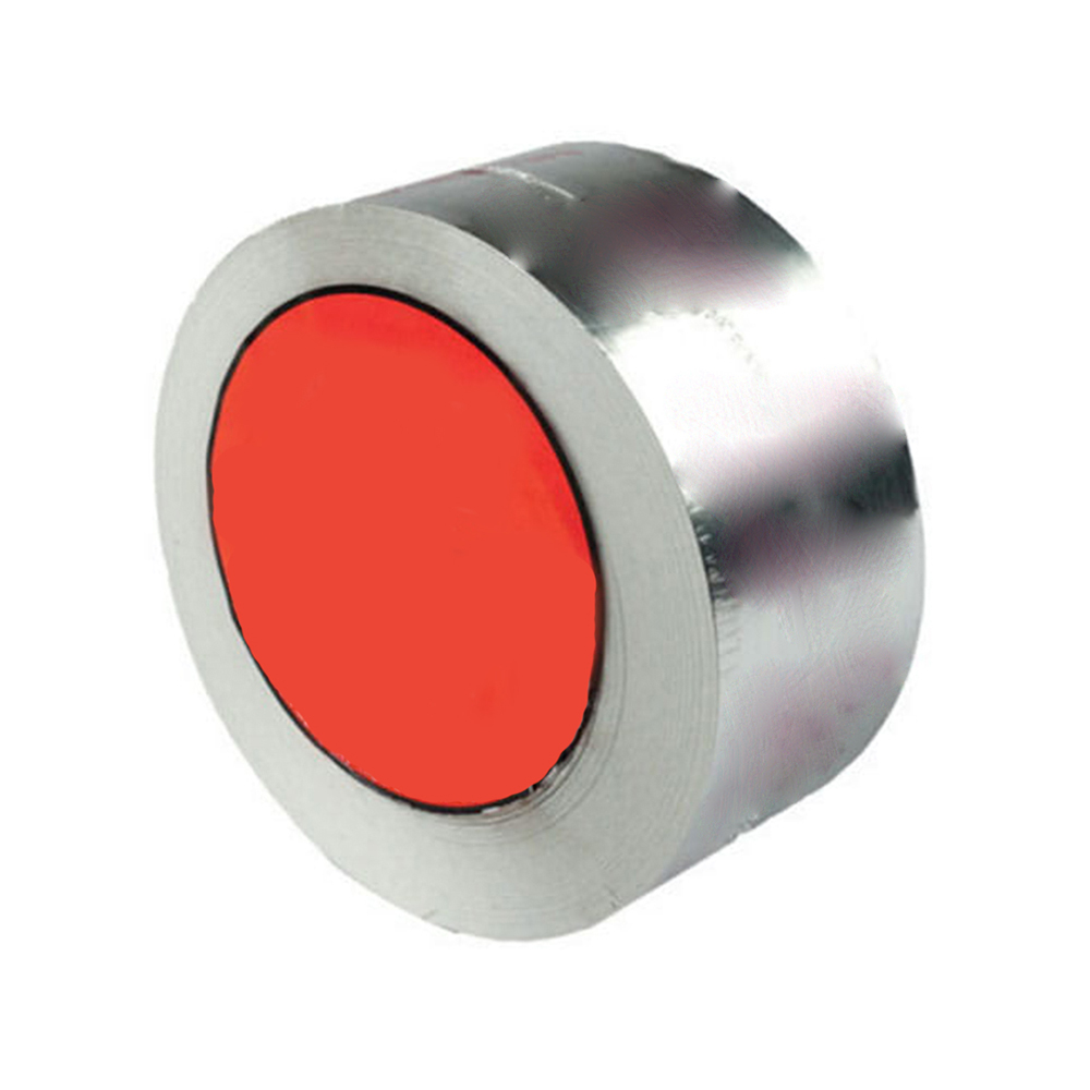 Trace Heater Installation Kits and Accessories Suppliers, Company - Jiangsu WeinWeineng Electric is China wholesale Trace Heaters Installation Kits and Accessories suppliers and Trace Heater Installation Kits and Acce...View Product →
Conclusion
Start with the cable outer diameter, then verify the thread standard, and then check whether the cable is armoured. Use metric and PG charts as a planning reference, but always confirm the exact clamping range with the manufacturer's datasheet. A few minutes of measurement at the site can prevent cable gland failures that cost far more than the gland itself.

 English
 русский
 Français
 Español
 عربى
عربى
