A maintenance team notices that a 2-inch water line has stayed above freezing through a cold night, even though the heat trace circuit has no adjustable thermostat at the pipe. The cable was cut from a reel on site, run through several valves, and terminated in a junction box. Nothing about the installation looks like a conventional heater with a fixed resistance.
The short answer is that a self-regulating heat trace cable is a parallel heater with a conductive polymer core that changes resistance as it warms. The warmer the cable becomes, the lower its power output; the colder it is, the higher its output. That behavior is built into the material, not into an external switch.
That explains why the cable can be cut to length and why output falls near a hot valve. It does not remove the need for a heat-loss calculation, circuit protection, controls, and proper commissioning.
The core answer: a conductive polymer acts as a built-in thermostat
Inside the cable, two parallel bus wires run the full length of the product. A carbon-loaded polymer core is extruded around them and bridges the conductors. When power is applied, current passes through the polymer between the bus wires, and the polymer's resistance turns that current into heat.
The polymer has a positive temperature coefficient. At low temperature, the material is relatively compact and carbon particles form many conductive paths, so resistance is low and output is high. As the cable warms, the polymer expands, the carbon particles move apart, and resistance rises. Current falls, and the cable produces less heat. This is the self-regulating effect.
Manufacturers publish an output curve rather than a single wattage. A cable rated at 10 W/ft at 10°C may deliver more at 0°C and less at 50°C. The pipe reaches a balance point where cable output equals heat loss. That balance point, not the nominal rating alone, determines whether the line stays above freezing or holds a process temperature.
What the cable layers do, and why construction matters
The core is only one layer. The complete construction determines where the cable can be used and how long it will last:
- Stranded, tin-plated copper bus wires carry current and allow parallel operation along the entire length.
- The conductive polymer core provides the heating and the temperature response.
- Thermoplastic or fluoropolymer insulation provides dielectric strength and temperature rating.
- A metallic braid provides an earth path and mechanical protection; the outer jacket handles moisture, chemicals, and abrasion.
Because the bus wires are parallel, a self-regulating cable can be cut to length and terminated in the field. Each segment between the bus wires heats independently, so a local fault is less likely to open the entire circuit than in a series constant-wattage cable. That is convenient, but it makes termination quality important: moisture at a splice can cause nuisance tripping or a low insulation resistance reading even when the heating core is sound.
How output changes on a real pipe
Self-regulation is local. If one section of cable lies under insulation and another is exposed, the covered section runs warmer and reduces its own output. That helps prevent hot spots, but it does not make overlap harmless. Two layers of cable can trap heat, push the jacket beyond its rating, and create a local burn-out risk. Follow the manufacturer's overlap rule and keep the cable in straight runs unless the design allows otherwise.
Sensor placement also matters. A thermostat or controller sensor should represent the pipe temperature, not the cable jacket or the ambient air. On a freeze-protection line, the sensor is often on the pipe surface opposite the cable and under the insulation. On a process line, the control scheme may use a pipe sensor, ambient sensor, or both.
Self-regulating versus constant wattage and mineral insulated
The choice is not about which cable is best in general. It is about the output curve, circuit length, temperature, and maintenance model that fit the line.
Comparison of common electric heat trace constructions for industrial pipe and equipment lines.
| Feature |
Self-regulating |
Constant wattage |
Mineral insulated |
| Output versus temperature |
Falls as the cable warms |
Stays close to a fixed value |
Stays fixed and can be very high |
| Circuit layout |
Parallel bus wires |
Parallel zones or series sections |
Series conductor |
| Field cutting |
Cut to length within the maximum circuit length |
Limited by zone design and cold-lead arrangement |
Factory lengths; field work is specialized |
| Overlap risk |
Still avoid overlap; heat can accumulate |
Higher risk; output does not reduce |
High risk; closely follow design limits |
| Typical fit |
Freeze protection, valves, short and medium lines |
Longer lines with stable wattage demand |
High temperature, harsh environments, high power |
| Control approach |
Thermostat or controller for isolation, alarms, and energy management |
Controller recommended for temperature and current monitoring |
Controller and high-temperature protection required |
Design checks before you order
Size the cable from heat loss, not from pipe diameter. A small line in a cold, windy location can need more output than a larger insulated line indoors.
- Calculate heat loss at the lowest ambient and the required maintain temperature, using insulation thickness, wind, indoor or outdoor exposure, and supports.
- Add a practical margin, then check the cable's maximum sheath temperature and area T-class. A larger cable is not automatically safer.
- Verify supply voltage, start-up current, breaker size, RCD protection, and maximum circuit length. Cold-start current can be several times the steady-state current.
- Confirm the area classification, ATEX or IECEx certification, chemical compatibility, UV exposure, and minimum installation temperature.
- Decide how the circuit will be controlled and monitored. Self-regulation reduces output, but it does not isolate a failed circuit or raise an alarm.
For freeze protection, the heat trace product family includes low-temperature and high-temperature constructions. The selection should match the pipe temperature and the environment, not just the pipe size.
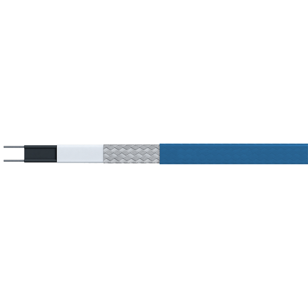 Low-Temperature Trace Heater for Frost ProtectionView this low-temperature trace heater for frost protection and low-temperature maintenance on pipes, tanks, valves, or equipment where moderate heat suits the pipe and environment.View Product →
In hazardous areas, the control cabinet is part of the safety boundary. It must match the area classification, contain the correct switching and protection, and provide a clear place for alarm and status signals.
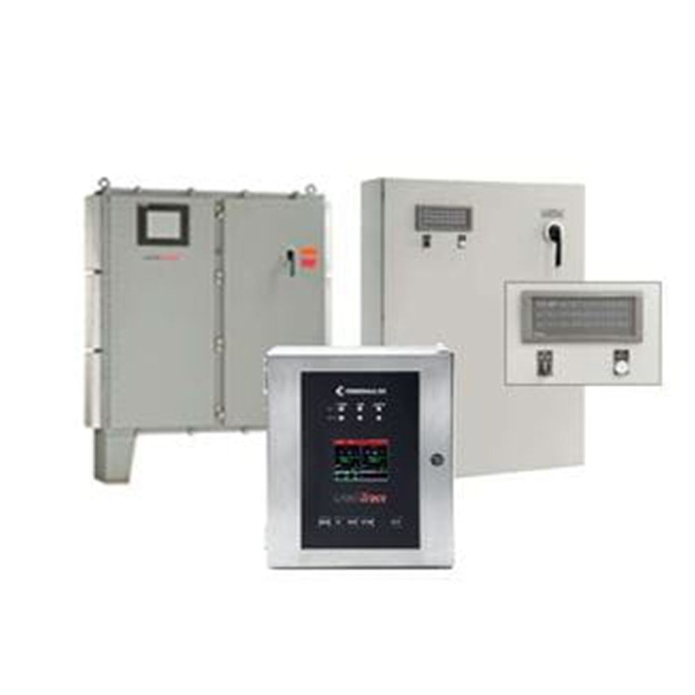 Heat Tracing Control Cabinet for Hazardous LocationsA control and monitoring cabinet for heat tracing systems with 1–72 circuits, suited to hazardous areas and freeze protection, de-icing, or process temperature maintenance.View Product →
Installation, commissioning, and inspection
Most callbacks come from installation details rather than the heating core: a wet splice, a crushed cable, a sensor in the wrong place, or an insulation resistance reading that was never recorded before the pipe was covered.
The construction techniques and inspection standards for electric heat tracing are a useful checklist: cable layout, attachment, thermal insulation, labeling, and electrical tests.
- Test insulation resistance before covering the cable, after insulation, and before energizing. Record the readings.
- Keep splices dry and mechanically protected; use the correct kit for the jacket and area classification.
- Install the sensor in a representative location and set the controller to the required maintain temperature.
- Energize and measure operating current after the line reaches a stable temperature. Compare it with the published output curve.
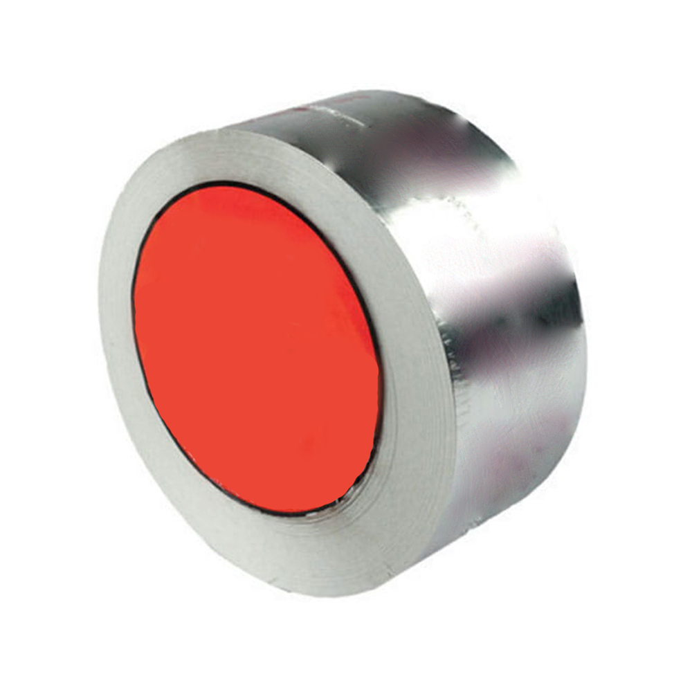 Heat Trace Installation Kits and AccessoriesSplices, connection boxes, end seals, tapes, straps, and RTDs for reliable heating cable installation, supporting inspection and commissioning checks on pipes, roofs, and vessels.View Product →
Commissioning should include an RCD trip test, alarm test, and a check that the circuit is labeled at both the panel and the pipe.
Common failure points and how to avoid them
Self-regulating cable is forgiving, but it is not self-diagnosing. Common problems are predictable: wrong voltage, moisture in a junction, damaged jacket, crushed cable under insulation, overlapping cable, a sensor in the wrong place, and a circuit without RCD protection. A cable that is still energized can also fail to heat if a bus wire is broken or a termination has lost contact.
Use the output curve for troubleshooting. If current is lower than expected, check supply voltage, circuit length, and termination. If current is higher than expected, check for a short, the wrong cable, or a cold line that has not reached balance. Thermal imaging can help, but it should be used with the insulation removed or through a suitable viewing port.
Self-regulation is a material property, not a substitute for engineering. The cable adjusts its output, while the designer still has to calculate heat loss, select protection, and prove the installation. Get those steps right, and the cable will do the quiet work it was chosen for.

 English
 русский
 Français
 Español
 عربى

