What Is Heat Tracing and Why Industrial Piping Needs It
Pipe freezing is not just a winter inconvenience — in industrial facilities, a single frozen line can halt an entire production process, damage equipment, and create safety hazards that take days to resolve. Heat tracing addresses this directly by applying a controlled source of external heat along the length of a pipe, maintaining the fluid inside at a target temperature regardless of ambient conditions.
The principle is straightforward: a heating element runs parallel to — or wraps around — the pipe, covered by thermal insulation to minimize heat loss. The combination of active heat input and passive insulation keeps the pipe surface and its contents within a defined temperature window. Depending on the application, that window might be just above 0°C for freeze protection, or well above 100°C for maintaining the flow viscosity of heavy oils, bitumen, or molten sulfur.
Three distinct operational needs drive heat trace adoption in industrial settings. Freeze protection is the most common — water, instrument lines, and process fluids must stay above their freezing point during cold weather shutdowns or low-flow periods. Temperature maintenance addresses fluids that must remain within a specific range to stay pumpable or chemically stable; viscous crude, wax-forming hydrocarbons, and certain chemicals all fall into this category. Process temperature control goes further, using trace heating as a precision tool to hold a fluid at exact operating conditions — critical in pharmaceutical manufacturing, food processing, and specialty chemical production.
Explore the complete heat trace product line for industrial piping to understand the range of cable types and accessories available for each application tier.
Electric vs. Steam Heat Tracing: Choosing the Right System
Two fundamentally different technologies dominate industrial pipe heat tracing: fluid-based systems (primarily steam tracing) and electric resistance heat tracing. Both can achieve the same end result, but they differ substantially in installation complexity, operating cost, controllability, and suitability for different plant environments.
Steam tracing has been the default choice in petrochemical and refinery settings for decades, largely because steam infrastructure was already present. A small-bore steam tube runs alongside the process pipe, transferring heat through contact and condensation. The system requires no electrical supply at the pipe, and steam's high latent heat makes it effective for high-heat-load applications. The drawbacks are significant, however: steam systems require condensate return infrastructure, are difficult to control precisely, and carry a higher risk of overheating sensitive products. Maintenance costs accumulate from steam trap failures, condensate corrosion, and insulation degradation.
Electric heat tracing has displaced steam in a growing share of new projects and retrofits. Installation is simpler — no steam supply lines, no condensate return, no trap maintenance. Temperature control is far more precise, with modern controllers capable of holding pipe temperatures within ±1–2°C of setpoint. Energy consumption is also lower in most applications, since electric systems heat only when needed rather than continuously circulating steam. For facilities without existing steam infrastructure, electric trace is almost always the more cost-effective choice from day one.
Electric vs. steam heat tracing: key comparison factors
| Factor |
Electric Heat Tracing |
Steam Heat Tracing |
| Installation complexity |
Low — cable, insulation, controller |
High — piping, traps, condensate return |
| Temperature control precision |
±1–2°C with electronic controller |
Limited, depends on steam pressure |
| Operating cost |
Low — energized only when needed |
Higher — continuous steam circulation |
| Maintenance requirements |
Low — periodic inspection |
High — trap failures, condensate corrosion |
| Max. temperature capability |
Up to 650°C (MI cable) |
Typically limited by steam supply pressure |
| Best suited for |
New projects, precise temperature needs |
Facilities with existing steam infrastructure |
Types of Electric Heat Trace Cables
Electric heat trace cables are not a single product — they span a range of designs that differ in how they generate and distribute heat, their maximum exposure temperature, and how they respond to changing pipe conditions. Selecting the right cable type is the most consequential specification decision in any heat trace project.
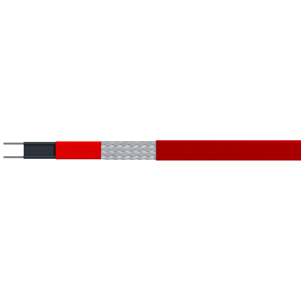
Self-regulating (self-limiting) cables are the most widely used type for freeze protection and low-to-medium temperature maintenance. Their defining characteristic is a conductive polymer core that automatically adjusts heat output in response to pipe temperature: as the pipe warms, the core's resistance increases and power output drops; as the pipe cools, resistance falls and output rises. This self-regulation prevents overheating and allows cables to be overlapped without risk of burnout — a significant installation advantage on complex pipe geometries. Typical continuous exposure temperatures range from 65°C to 120°C depending on cable grade.
Constant wattage cables output a fixed amount of heat per unit length regardless of pipe temperature. They are the right choice when a precise, uniform heat flux is required across the full pipe length — common in viscous fluid temperature maintenance and long pipeline applications. The flexible constant-power heating cable for temperature maintenance covers the core requirements of these applications, offering stable watt-per-meter output across varying ambient conditions. Because constant wattage cables cannot self-regulate, proper thermostat control is mandatory to prevent overheating.
Mineral insulated (MI) cables represent the high-performance tier of electric heat tracing. Constructed with a metal sheath, magnesium oxide insulation, and a resistance wire core, MI cables withstand continuous operating temperatures up to 650°C and are inherently robust in chemically aggressive, mechanically demanding, or classified hazardous area environments. They are the standard choice for high-process-temperature applications in refineries and chemical plants. The high-temperature special heating cable for demanding process lines is designed for exactly these conditions, delivering reliable performance where polymer-insulated cables cannot operate safely.
Electric heat trace cable types and typical specifications
| Cable Type |
Max. Continuous Temp. |
Self-Regulating |
Typical Application |
| Self-regulating |
65°C – 120°C |
Yes |
Freeze protection, water lines, moderate temperature maintenance |
| Constant wattage |
120°C – 200°C |
No |
Viscous fluid maintenance, long pipelines |
| Mineral insulated (MI) |
Up to 650°C |
No |
High-temp process lines, refinery, chemical plant |
Key Applications Across Industries
Heat tracing for piping appears across virtually every sector of process industry, but the dominant requirements vary significantly by application.
Oil and gas / petrochemical operations represent the largest single market for industrial heat tracing. Crude oil, heavy fuel oil, and a wide range of hydrocarbon intermediates become too viscous to pump at ambient temperatures — heat tracing keeps transfer lines, storage tank outlets, and loading/unloading headers pumpable around the clock. Sulfur lines, which solidify at approximately 119°C, are a particularly demanding application that typically requires constant wattage or MI cable. Hazardous area classification (Zone 1 or Zone 2 in most installations) adds an explosion-proof requirement to all electrical components.
Water and wastewater utilities rely on heat tracing primarily for freeze protection of exposed water mains, instrument lines, valve actuators, and sampling points in cold-climate installations. Self-regulating cable is the dominant technology here — energy efficient, easy to install on irregular geometries, and safe to operate without constant supervision.
Food and beverage processing uses heat tracing to maintain product temperature in transfer lines — chocolate, edible oils, syrups, and similar products must stay within narrow temperature bands to preserve viscosity, texture, and quality. Hygienic installation requirements and frequent cleandown cycles add specific demands around cable jacketing material and junction box ingress protection ratings.
Pharmaceutical manufacturing applies heat tracing in clean-utility systems and active pharmaceutical ingredient (API) transfer lines. Temperature uniformity is critical; even brief cold spots can cause crystallization or precipitation that contaminates a batch. The freeze protection and high-temperature trace heater serves both ends of this spectrum — low-temperature utility protection and high-temperature process line maintenance — within a single product family.
Chemical and specialty materials production covers an enormous range of fluids with highly specific temperature requirements: polymer melts, adhesives, resins, and reactive intermediates that must be kept within tight windows to remain processable and chemically stable.
How to Size and Select a Heat Trace System
Heat trace system design begins with a heat loss calculation — determining how much thermal energy the pipe loses to its surroundings per unit length, and therefore how much the trace heating system must supply to maintain the target temperature. Getting this number right is the foundation of a system that neither under-performs in cold weather nor wastes energy in moderate conditions.
The key inputs to a heat loss calculation are: pipe outside diameter, insulation type and thickness, target pipe maintenance temperature, minimum expected ambient temperature, and the presence of wind exposure. Larger diameter pipes have greater surface area and therefore higher absolute heat loss; thicker insulation reduces the required cable output and is almost always more cost-effective over the system's lifetime than increasing cable wattage. A rule frequently encountered in engineering practice is that doubling insulation thickness roughly halves the required trace heating capacity.
Once heat loss is established, cable selection follows by matching the required watts-per-meter output to the appropriate cable type and spacing. For self-regulating cables, the cable output at the minimum ambient temperature (not at pipe temperature) determines adequacy. For constant wattage cables, the output is fixed, so the design must ensure the cable cannot overheat the pipe at maximum ambient conditions or during low-flow periods when the pipe temperature rises.
IEEE 515-2017, the IEEE standard governing the testing, design, installation, and maintenance of electrical resistance trace heating for industrial applications, provides the recognized framework for qualifying heat trace systems and verifying that designs meet thermal and electrical safety requirements. Specifying IEEE 515-compliant products is the baseline expectation for major industrial projects and EPC contractor requirements worldwide.
Circuit length limits are a practical constraint that shapes system layout. Self-regulating cables are limited by voltage drop over long runs; constant wattage parallel-resistance cables can cover significantly longer circuits without derating. For large-scale installations, working with the cable manufacturer's design tools — or engaging a specialist engineer — to model circuit lengths, breaker sizing, and ground-fault protection levels is standard practice.
Control Systems and Monitoring for Heat Trace
A heat trace cable without proper controls is an incomplete system. Controls determine when the heating circuit energizes, protect against overtemperature conditions, and — in modern installations — provide fault monitoring that flags problems before they cause process failures.
Three control strategies cover the majority of industrial heat trace applications. On/off ambient-sensing control uses an ambient air thermostat to energize the circuit below a set temperature (typically 5–10°C) and de-energize it above. Simple and low-cost, this approach works well for basic freeze protection but cannot account for wind chill, solar gain, or fluid flow conditions that affect actual pipe temperature. Proportional pipe-sensing control uses a temperature sensor attached directly to the pipe surface, providing tighter regulation and better energy efficiency — the circuit runs only as much as needed to hold the pipe at setpoint. Advanced electronic controllers incorporate both ambient and pipe-sensing inputs, ground-fault detection, alarm outputs, and data logging — the preferred configuration for critical process lines or large multi-circuit installations.
In hazardous area installations — Zone 1 and Zone 2 classified locations covering most of the oil and gas and chemical sectors — all electrical components in the heat trace system must carry appropriate explosion-proof or increased-safety certifications. This requirement extends to junction boxes, end terminations, and control panels, not just the heating cable itself. The hazardous location heat trace control cabinet addresses this requirement directly, providing a certified enclosure that integrates temperature control, circuit protection, and monitoring in a single panel rated for classified environments.
Ground-fault protection deserves specific attention. Heat trace circuits operating outdoors or in wet process environments are exposed to moisture ingress at terminations and splice points. Ground-fault circuit interruption (GFCI) protection set at 30–100 mA trip threshold is the industry standard for personnel protection and cable protection — it detects leakage current that indicates insulation degradation before it reaches a level that causes cable failure or poses a shock risk to maintenance personnel.
For large facilities, centralized monitoring systems that poll each heat trace circuit and report status, energy consumption, and fault conditions to a control room or SCADA platform represent the current direction of the technology. The economic case is straightforward: a single undetected cable failure on a critical line can cost far more in process downtime and repair than the monitoring infrastructure required to catch it early.
 English
 русский
 Français
 Español
 عربى
عربى