Every pipe carrying a fluid above ambient temperature is losing heat — continuously, unavoidably, through its walls and into the surrounding environment. In most cases, insulation slows this process enough that it doesn't matter. In some cases, it matters enormously: a water line that freezes overnight shuts down a facility; a viscous chemical that drops below its pour point blocks a process for hours; an instrument impulse line that ices over gives false readings at the worst possible moment. Electrical trace heating exists to solve exactly these problems — by adding compensating heat directly along the pipe surface, continuously or on demand, in precise quantities matched to the heat being lost.
Why Pipes Lose Heat and What Trace Heating Does About It
Heat flows from hot to cold. Any pipe carrying fluid warmer than the surrounding air will lose thermal energy through its wall, through any insulation applied to it, and ultimately into the atmosphere. The rate of that loss depends on the temperature differential between the fluid and the environment, the pipe diameter and wall thickness, the insulation type and thickness, wind speed, and ambient temperature.
Insulation reduces heat loss but cannot eliminate it. A well-insulated pipe in a cold environment still loses heat — just more slowly. When the environment is cold enough, or when the fluid inside must stay above a specific temperature for safety or process reasons, insulation alone is insufficient. Something must actively replace the heat being lost.
Electrical trace heating solves this by applying a compensating heat source directly to the pipe surface. A heating cable runs along the outside of the pipe — or in some configurations, inside it — generating thermal energy through electrical resistance. That energy transfers conductively into the pipe wall and from there into the fluid. With thermal insulation applied over the cable, heat losses to the environment are minimized and the fluid temperature stays within the required range.
The result is a system that doesn't heat the fluid from scratch — it replaces only the heat that would otherwise be lost. This makes trace heating highly energy-efficient compared to bulk heating approaches, particularly in applications where the fluid temperature target is modest and the primary goal is freeze protection or flow maintenance rather than temperature elevation.
How Electrical Trace Heating Works
At its core, electrical trace heating converts electrical energy into heat through resistance — the same physical principle that makes a wire warm when current passes through it. A heating cable consists of one or more conductive elements that resist the flow of electricity, generating heat proportional to the current and the resistance value. That heat conducts outward through the cable's outer sheath and into the pipe surface it contacts.
The cable is fixed to the pipe using aluminum tape or attachment clips to maximize contact area and improve heat transfer. Thermal insulation is then applied over the entire assembly — pipe, cable, and all — to trap the generated heat and minimize loss to the environment. A thermostat or electronic controller monitors pipe or ambient temperature and switches the cable circuit on and off to maintain the target temperature setpoint.
Power supply connections, junction boxes, and end terminations complete the electrical circuit. In industrial installations, ground-fault circuit protection is standard — it detects leakage current and disconnects the circuit before a fault can cause damage or create a safety hazard.
Our heat trace systems for industrial pipe and equipment protection are engineered for demanding environments — from routine freeze protection on water lines to high-temperature process maintenance on chemical pipelines — with configurations suited to both classified and non-classified installation areas.
The Three Main Types of Trace Heating Cables
Not all trace heating cables work the same way. Three principal types are used in industrial and commercial applications, each with distinct performance characteristics, installation requirements, and optimal use cases.
Self-regulating cables are the most widely used type in modern trace heating installations. Their defining feature is a conductive polymer core — a matrix of carbon particles embedded in a polymer material — that sits between two parallel bus wires. When temperature drops, the polymer contracts slightly, the carbon particles move closer together, resistance decreases, and the cable outputs more heat. When temperature rises, the polymer expands, carbon particles separate, resistance increases, and output drops automatically. The cable regulates its own power output in response to local temperature — without any external controller.
This self-limiting behavior means self-regulating cables cannot overheat themselves, can be overlapped or cut to length in the field, and are inherently energy-efficient. They are the standard choice for freeze protection on water piping, instrument tubing, and general process lines where maintain temperatures fall below 150°C. Their limitation is upper temperature ceiling — they are not suitable for very high-temperature process applications.
Constant wattage cables (also called series resistance or parallel resistance cables) output a fixed amount of heat per unit length regardless of temperature. Series resistance cables are a single continuous resistive element — the same current runs through the entire circuit, and output cannot be varied in the field. Parallel resistance cables use a resistive element wound around two bus wires, allowing the circuit to be cut to specific lengths without affecting output per unit length. Both types require external thermostatic control to prevent overheating. Their advantage is the ability to deliver consistent, predictable output over long runs and at higher temperatures than self-regulating cables can achieve.
Mineral insulated (MI) cables are the high-performance tier of trace heating technology. A mineral insulated cable consists of one or more resistance wires surrounded by compressed magnesium oxide powder inside a metal sheath — typically stainless steel or Inconel. The result is a cable capable of operating at temperatures up to 600°C or beyond, with excellent mechanical strength and resistance to chemical attack. MI cables are the standard for steam line tracing, high-temperature process piping, and applications in aggressive chemical environments where polymer-insulated cables would degrade. They cannot be cut to length in the field and require factory-fabricated terminations.
Comparison of the three main trace heating cable types
| Cable Type |
Max Maintain Temp |
Field Cut to Length |
Self-Limiting |
Best For |
| Self-Regulating |
Up to ~150°C |
Yes |
Yes |
Freeze protection, general process maintenance |
| Constant Wattage (Parallel) |
Up to ~200°C |
Yes (parallel type) |
No |
Long runs, consistent output, higher temp applications |
| Mineral Insulated (MI) |
Up to 600°C+ |
No |
No |
High-temperature process lines, aggressive environments |
Industrial Applications: Where Electrical Trace Heating Is Used
Electrical trace heating appears across a broad range of industries. The common thread is the need to maintain fluid temperature in a system where heat loss would otherwise cause operational, safety, or quality problems.
Oil and gas processing is the largest industrial consumer of trace heating systems. Crude oil, heavy fuel oil, and certain refined products become too viscous to pump efficiently at ambient temperature. Waxy crudes can solidify in pipelines during shutdown periods, requiring hours of reheating before flow can be restored. Trace heating on transfer lines, storage tank outlets, and instrument impulse lines keeps these fluids mobile and measurement systems accurate throughout the production process.
Chemical and petrochemical plants use trace heating extensively on process piping carrying substances that freeze or crystallize above ambient temperature — sulfur, caustic soda, phosphoric acid, and hundreds of specialty chemicals all require maintained temperatures to remain pumpable. In hazardous classified areas, explosion-proof cable and termination components are mandatory.
Water and wastewater infrastructure relies on freeze protection trace heating wherever piping passes through unheated spaces, is exposed to outdoor conditions, or is buried in frost-prone soils. Municipal water mains, fire suppression sprinkler lines, and instrument sensing lines in outdoor enclosures are all common trace heating applications in this sector.
Food and beverage manufacturing uses trace heating to maintain temperature on lines carrying chocolate, oils, syrups, sauces, and other food products that must stay within defined viscosity ranges during transfer and processing. Sanitary-grade cable construction and CIP-compatible installation are required in these environments.
Power generation facilities apply trace heating to fuel oil systems, cooling water circuits, and instrumentation in cold climate installations. Coal handling conveyors and ash slurry lines at power stations also frequently require freeze protection in northern regions.
Building services and commercial applications include roof and gutter de-icing, floor warming, hot water recirculation maintenance, and freeze protection for sprinkler systems in unconditioned spaces.
Key Design Parameters for Electrical Trace Heating Systems
A trace heating system that is undersized fails to maintain temperature; one that is oversized wastes energy and can damage pipe coatings or seals. Correct system design requires working through several interdependent parameters before specifying cable type, wattage, and control equipment.
Maintain temperature and minimum ambient temperature. The maintain temperature is the minimum fluid temperature that must be preserved under all operating conditions. The minimum ambient temperature is the coldest environment the pipe will experience — often the design winter low for the installation location. The difference between these two values, combined with the pipe diameter and insulation specification, determines the heat loss rate that the trace heating system must compensate.
Heat loss calculation. Heat loss is calculated per unit length of pipe, accounting for pipe diameter, insulation type and thickness, ambient temperature, and wind exposure. Valves, flanges, pipe supports, and other fittings lose heat faster than straight pipe sections and require additional cable length or higher-output segments. Most industrial trace heating designs apply a safety factor of 1.25 to 1.5 over the calculated heat loss to ensure performance margin.
Control system selection. Simple freeze protection applications can use mechanical thermostats set to switch the circuit on when ambient temperature drops below a threshold. Process temperature maintenance applications require more precise control — electronic temperature controllers with RTD or thermocouple sensors mounted directly on the pipe surface. Our industrial heating control systems support both single-point and multipoint temperature monitoring with programmable setpoints, alarm outputs, and data logging for process documentation requirements.
Area classification. Pipelines in oil and gas, chemical, and petrochemical facilities frequently pass through areas classified as hazardous due to the potential presence of flammable gases or vapors. Trace heating components installed in these zones — cables, power connection boxes, thermostats, and junction boxes — must be certified for the applicable area classification under ATEX, IECEx, or North American Class/Division standards.
Standards and Compliance: IEEE 515, NFPA 70, and Hazardous Area Requirements
Electrical trace heating installations in industrial and commercial facilities are subject to a framework of standards that govern design, installation, testing, and maintenance. Working within this framework is not optional — it is a prerequisite for insurance coverage, facility operating permits, and the confidence that the system will perform safely over its service life.
IEEE 515 is the primary standard governing electrical resistance trace heating for industrial applications. It specifies test requirements for qualifying heating cables, establishes the basis for electrical and thermal design, and addresses installation and maintenance requirements for both unclassified areas and North American hazardous area classifications. The IEEE Standard for the Testing, Design, Installation, and Maintenance of Electrical Resistance Heat Tracing for Industrial Applications is the authoritative reference for engineers specifying and certifying industrial trace heating systems.
NFPA 70 (National Electrical Code) governs the electrical installation aspects of trace heating systems in the United States — wiring methods, overcurrent protection, ground-fault protection, and the requirements for installations in hazardous classified locations. Compliance with NEC Article 427 (fixed electric heating equipment for pipelines and vessels) is mandatory for US installations.
ATEX and IECEx are the European and international certification frameworks for electrical equipment used in explosive atmospheres. Trace heating equipment installed in Zone 0, 1, or 2 hazardous areas under IEC area classification must be certified under the applicable ATEX directive or IECEx scheme, with sheath temperature limits verified against the auto-ignition temperature of the hazardous substance present.
For facilities supplying products into regulated markets, maintaining documentation of cable test certificates, area classification drawings, installation records, and periodic inspection reports is part of ongoing compliance. Selecting equipment from manufacturers with recognized certifications significantly simplifies this documentation burden.
Pairing Trace Heating with Industrial Heaters for Complete Thermal Management
Trace heating handles the distributed challenge — maintaining temperature along the length of a pipeline or across a vessel surface. It is not, by itself, a bulk heating solution. For applications that also require heating large volumes of fluid in storage tanks, heating process streams before they enter a pipe system, or bringing cold-started equipment up to operating temperature, trace heating works in combination with other industrial heating technologies.
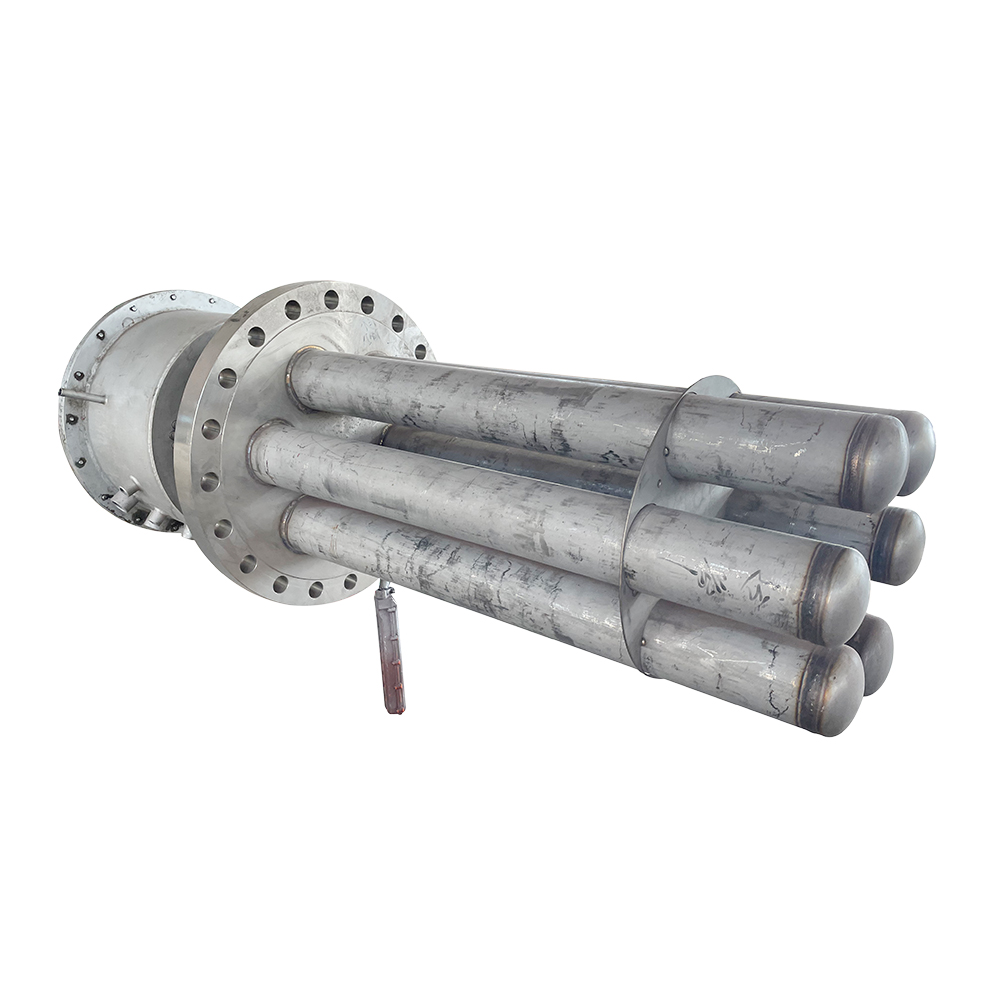
Immersion heaters installed directly in storage tanks maintain the bulk temperature of heavy fuel oils, chemical solutions, and process fluids while trace heating handles the connected transfer piping. In hazardous locations — fuel storage areas, chemical plants, offshore platforms — explosion-proof immersion heaters for hazardous area tank heating provide the certified construction required for safety in classified environments. For standard industrial storage applications, flange immersion heaters for storage tank temperature maintenance offer high power density in a compact, easily serviceable format.
Process heaters heat gases, liquids, and two-phase streams flowing through dedicated heating vessels before they enter the distribution piping system. They are the primary heating stage; trace heating is the temperature maintenance stage downstream. Our industrial process heaters for fluid and gas heating applications cover a wide power range — from compact compressed-air heaters to high-capacity explosion-proof units for oil and gas service — with configurations for both inline and skid-mounted installations.
The most effective industrial thermal management systems treat trace heating and bulk heating as a coordinated architecture rather than separate solutions. Matching the heating capacity at each stage — storage tank, process heater, transfer line, instrument impulse line — to the actual thermal load at that point eliminates both underperformance and energy waste, and produces a system that operates reliably across the full range of ambient conditions the facility will experience.
 English
 русский
 Français
 Español
 عربى
عربى